Abstract:
In this blog post we go over how to we assembled the LoRa transmitter and receiver. We include instructions on how to set up the Arduino IDE as well as the code for our test devices.
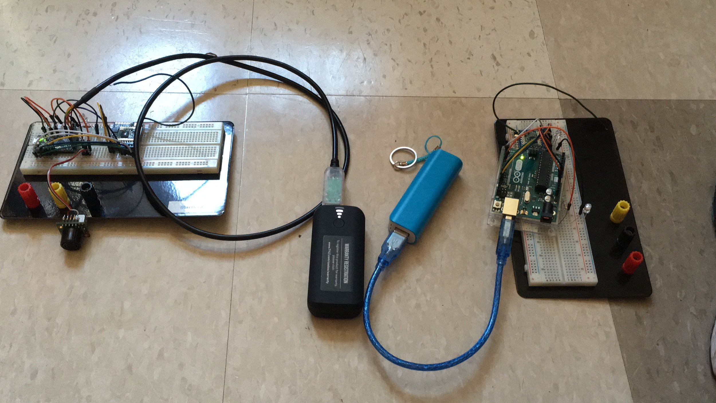
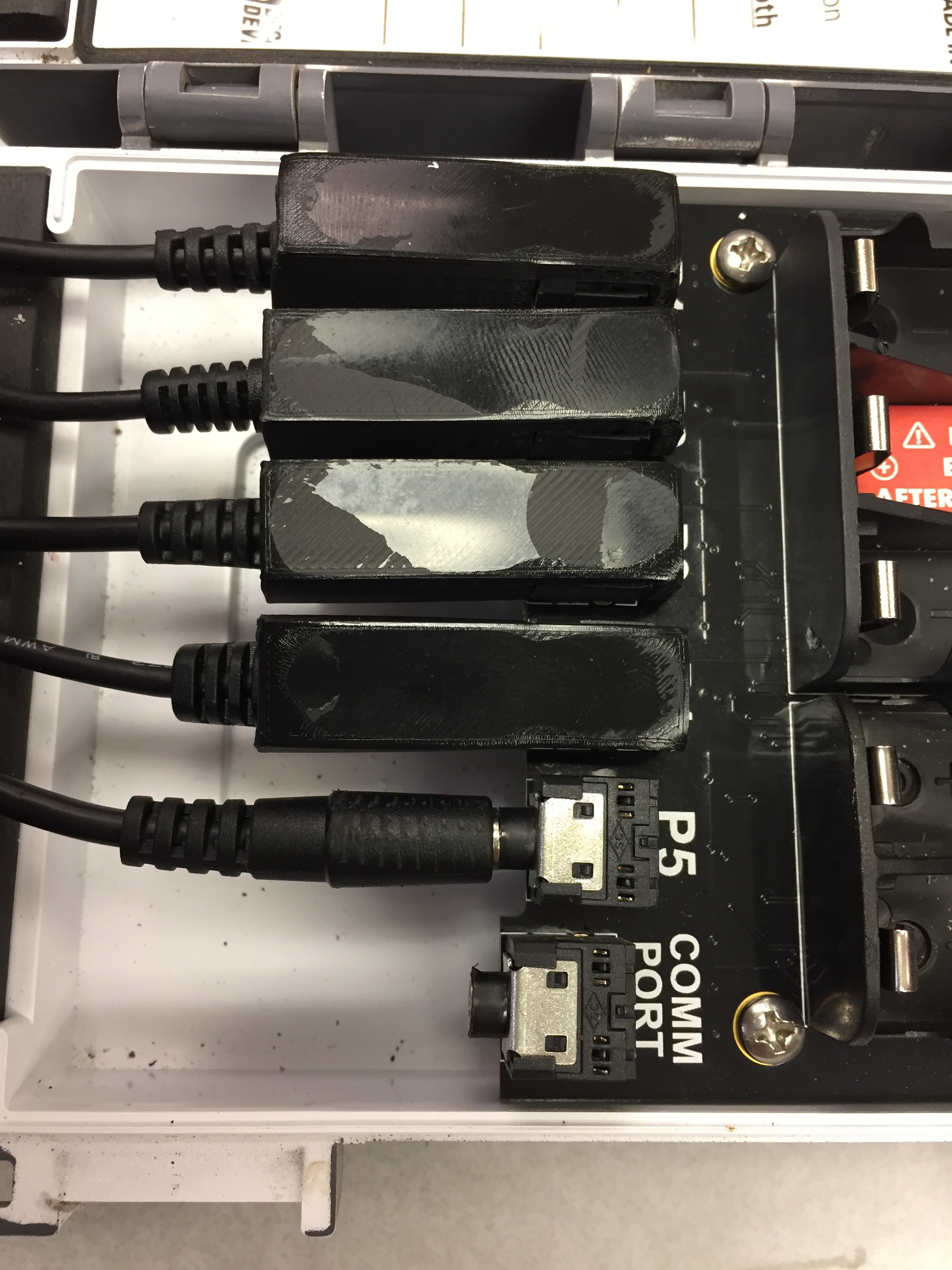
Update: Transmitter (left) and Receiver (right) on separate breadboards connected to portable 5V power sources
Materials:
These are the components connected to now separate transmitter/receiver (pictured above):
Transmitter:
– Matbotix 1220 sonar sensor
– RFM9X LoRa Radio
– Adafruit Pro Trinket (3V Logic) w/ FTDI cable connector
– Red LED
– 51 ohm resistor
Receiver:
– RFM9X LoRa Radio
– Arduino UNO (5V out) w/ macro USB cable connector
– 81 ohm resistor
– Red LED
– White LED
The transmitter and receiver have been placed on separate breadboards in order to test the range on the LoRa chips. Code on both the transmitter and receiver sketches has been rewritten to send and receive the data values measured by the MB1220. Other changes include the replacement of the Arduino Uno development board with the smaller 3V Adafruit Protrinket. If you haven’t already, you will need to set up your Arduino IDE so that it recognizes Adafruit’s development boards when plugged into the USB port using an FTDI cable.
SETTING UP THE ARDUINO IDE: You will need to go into Arduino’s Preferences, paste the Adafruit Board Support Package URL into the space next to “Additional Board Manager URLS”, click OK, then go into the Tools tab and select the “Boards Manager” found in “Boards:”. Filter your search by choosing “Contributed” from the dropdown menu and typing “Adafruit AVR” in the search bar. Then install the package “Adafruit AVR Boards”. Once installed, you can upload your Arduino sketches to the Pro Trinket by selecting “Pro Trinket3V/12MHz (FTDI)” from the Boards dropdown menu.
The Pro Trinket uses the Atmega328P chip – the same core chip as our Arduino UNO – making it easy to switch between the two. When transitioning to the Pro Trinket I realized it lacked pins #2 and #7 as well as the level shifting featured on the UNO (5V input on the Pro Trinket will have to be reduced to 3.3V to prevent damage to the board). To accommodate the Pro Trinket, I replaced interrupt Pin#2 for Pin#3 and digital write Pin#7 for Pin#6 and applied these changes to the UNO so the transmitter and receiver code can be used for either board. Here are the updated versions of the transmitter and receiver code.
I have provided links to more information about the Pro Trinket’s limitations compared to the UNO and step by step instructions for installing the Adafruit AVR package.
– Marissa Kwon Undergraduate Student Researcher