Nordic RF shields for Adafruit ProTrinket

By: Chet Udell

Abstract:

This post provides an update on the near-range (up to 100m) RF branch of the Internet of Agriculture Project. New PCB design makes an improvement on a general-purpose, opensource, plug-n-play wireless sensor kit.

Objective:

The previous version of the RF IoT sensor kit had some minor layout flaws, and failed to accommodate a ‘handshake’ button for auto synchronizing an RF sensor node with its base station, a power button, and some other small details. A new version adds these features and reduces the overall device volume by one-third.

Methods and Materials:

Eagle CAD was used to modify a previous version of the PCB. A whole new layout was explored that reduced overall device volume substantially and new features added including: power button, handshake button, removing 12VDC power adapter on base receiver (for now), placing LiPo Backpack on the underside of the transmitter, and creating a “stackable” offset for the ProTrinket, should anyone wish to make further shields to extend this devices capacity.

Results:

See below! PCBs are in the fab house now. . .


WASN_HonorsBrd.pngWASN_HonorsBrd.png


Toward Comparing RFID Moisture Performance with Industry Standards: Decagon

Author: Chet Udell


Abstract:

Our previous experiments have shown the RFID moisture sensor tags are in-fact reading gradual changes in soil moisture content. The next step is to compare the performance, consistency, and resolution of these tags to industry standard equipment to see how it measures up using Decagon Devices soil moisture sensors. In this post, Chet gets a 5TM Soil Moisture and Temperature Sensor chatting directly with an Arduino to deploy in experiments, and eventually integrate into the battery of available Internet of Ag sensors.

Objective:

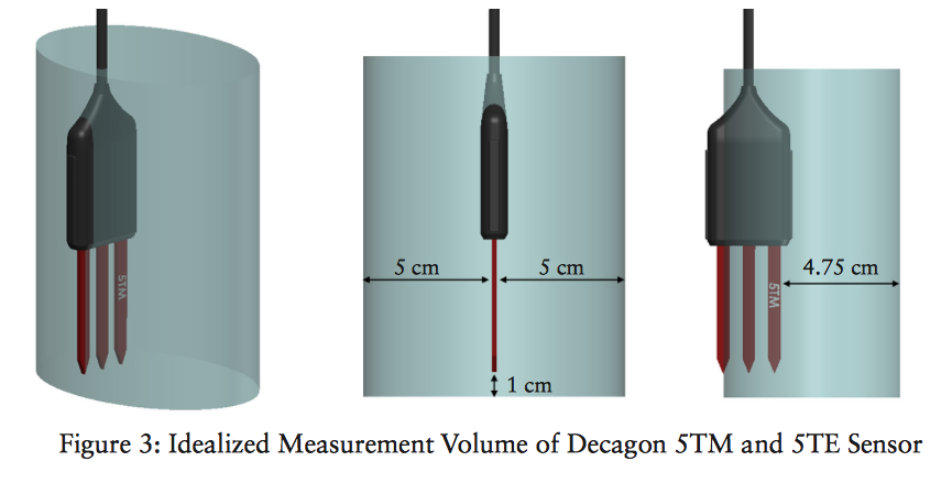
In order to compare the performance, consistency, and resolution of the RFID moisture tags, we hope to conduct some comparative experiments between these and Decagon’s popular soil moisture sensors, namely the 5TM (soil moisture + temp). Decagon’s readers can be pricey and we want to use these sensors in very specific ways, so the objective here is to get the sensors talking directly with an Arduino. The following method can be used to read any Decagon soil moisture sensor over the SDI-12 serial protocol. For more info on SDI-12, visit here. Why the 5TM? The 5TM determines volumetric water content (VWC) by measuring the dielectric constant of the soil (or other media) using capacitance/frequency domain technology. Signal filtering minimizes salinity and textural effects, making the 5TM accurate in most soils and soilless media. Factory calibrations are included for mineral soils, potting soils, rockwool, and perlite. – from http://www.decagon.com/en/soils/volumetric-water-content-sensors/5tm-vwc-temp/

Materials and Methods

What you’ll need:

  1. Download the above library, unzip. Rename the file “SDISerial” and place in the folder: <Arduinno root folder> / libraries
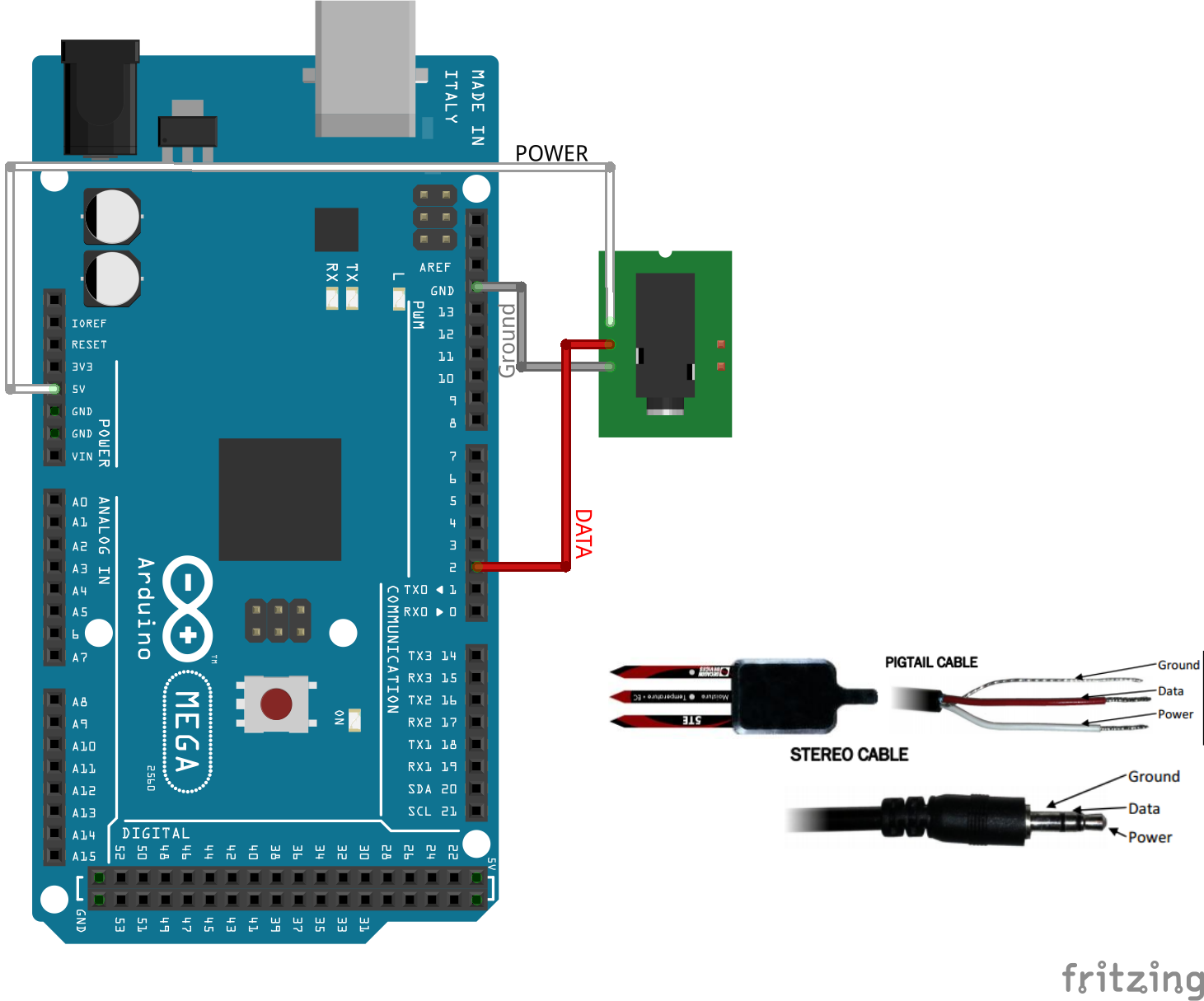
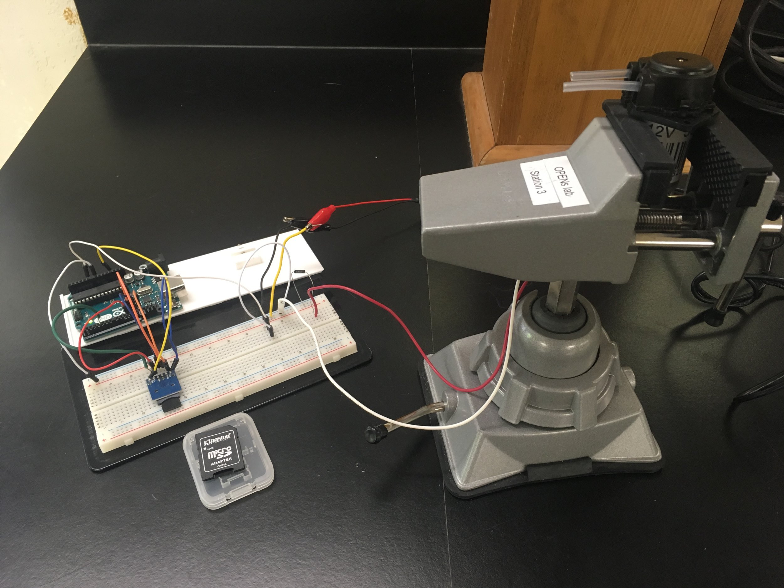
  2. Following the instructions on the library GitHub page (image included here), clip the 1/8 inch jack off of the Decagon sensor (ouch), strip off the leads to reveal a white, red, and “shield” wires. Solder each wire to a 0.1in pitch male header to use in a breadboard.
  3. Connect your arduino up to a breadboard and the 5TM lines White => 5V, Red => DATA_PIN, Shield => GND
  4. DATA_PIN MUST be connected to a pin with a hardware interrupt (for Uno, P2 or P3).
  5. Use the below code and you’ll get soil moisture and temp readings (in Celsius).
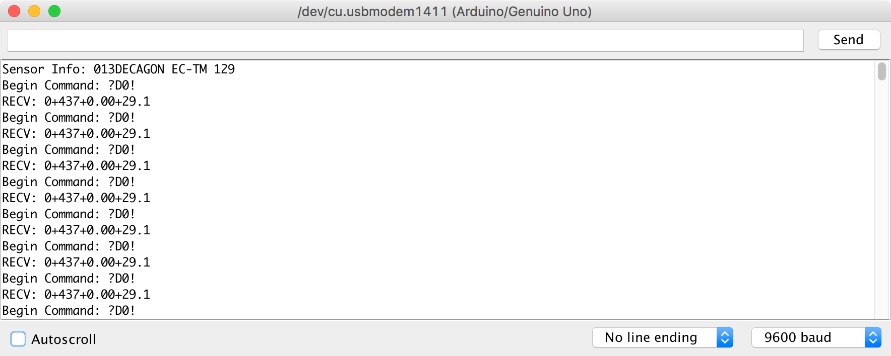
  6. Your output will look like the below screen print

Results

As you’ll see from the below code and printout, the SDISerial library enables the arduino to send commands to the 5TM to procure data. Now, we can employ these sensors in almost any Arduino application! This is done by creating an instance of SDISerial connection(DATA_PIN); and then starting the serial connection using connection.begin();

You can then use the function connection.sdi_query() to send various commands to the 5TM. This function uses 2 parameters: (command, timeout-duration)

connection.sdi_query(“?M!”,1000); This sends a message to query the first device on the bus – which in use seems to refresh the values of the sensor readings, but does not return the sensor reading itself. Instead, it returns a message that tells you the maximum wait before the measurement is ready. timeout set for one second.

connection.sdi_query(“?I!”,1000); will get sensor info and timeout if no response in 1 second

connection.sdi_query(“?D0!”,1000); will query the 5TM for sensor data


Hookup on a Mega, similar to the Uno


Resulting output
/*
Tested on UNO R3.
Sketch was built with Arduino 1.6.12
Dependency: Joran Beasley SDISerial Library
Accessed May 26, 2017 here:
https://github.com/joranbeasley/SDISerial

download and rename folder "SDISerial" and place in  "<ARDUINO_ROOT>/libraries"

Tested with the with the 5TM Soil Moisture and Temp Sensor:
http://www.decagon.com/en/soils/volumetric-water-content-sensors/5tm-vwc-temp/

Hook-up:
the WHITE wire goed to 5V. however you could also connect it to a pin and drive power only when you wanted it
the RED wire is the DATA_PIN. - you must hook it up to a pin that can process interrupts (see link below)  
the remaining "shield" wire must be connected to ground
*/

#include <SDISerial.h>
#include <string.h>
#define DATA_PIN 2
SDISerial connection(DATA_PIN);
char output_buffer[125]; // just for uart prints
char tmp_buffer[4];
char* resp; // Pointer to response char

//initialize variables
void setup(){
      connection.begin();
      Serial.begin(9600);//so we can print to standard uart
      //small delay to let the sensor do its startup stuff
      delay(3000);//3 seconds should be more than enough
      char* sensor_info = connection.sdi_query("?I!",1000); // get sensor info
      //print to uart
      sprintf(output_buffer,"Sensor Info: %s",sensor_info?sensor_info:"No Response");
      Serial.println(output_buffer);
}

//main loop
void loop(){

   //print to uart
    Serial.println("Begin Command: ?M!");   
    //send measurement query (M) to the first device on our bus
    resp = connection.sdi_query("?M!",1000);//1 second timeout
    //this really just returns a message that tells you the maximum wait before the measurement is ready
    
    sprintf(output_buffer,"RECV: %s",resp?resp:"No Response Recieved!!");
    Serial.println(output_buffer);
    delay(1000);//sleep for 1 seconds before the next command
    
    //print to uart
    Serial.println("Begin Command: ?D0!");
    resp = connection.sdi_query("?D0!",1000);//1 second timeout
    
    sprintf(output_buffer,"RECV: %s",resp?resp:"No Response Recieved!!");
    Serial.println(output_buffer);
    delay(3000);//sleep for 10 seconds before the next read
  
}

A Simple Pump Test

Introduction

Peristaltic 12V dosing pumps are cheap and provide a large enough volumetric flow rate for our needs. Unfortunately there is not much information available on the type we are using. This post will discuss the method we are using to test the reliability and consistency of these pumps over a period of two hours. It is the first of several tests we will be conducting on different components of our water sampler.


Setup and Method

A pump is held in a clamp and powered from a 12v source. A .85 ohm, 1.4 watt rated resistor connects the pump to ground. The voltage across the .85 ohm resistor is measured over time using an arduino and this data is stored in an SD card. 

The arduino reads the voltage on an analog pin and stores that, along with the time since starting in milliseconds, in the SD card. Initially there is a delay of one second in between data points and after sixty points the delay increases to one minute. This data will be transferred to a computer where it will be used to show the current through the pump over time.


Code:

// A simple voltage logger that is heavily
// based on the SD Datalogger example sketch.

#include <SPI.h>
#include <SD.h>

const int chipSelect = 4;
const int sensorPin = 0;

int n = 0;

void setup() {
  Serial.begin(9600);
  while(!Serial){
    ;
  }

  Serial.print(“Initializing SD card…”);

  if(!SD.begin(chipSelect)){
    Serial.println(“Card failed, or not present.”);
    return;
  }
  Serial.println(“card initialized.”);

}

void loop() {
    String dataString = makeDataString();
    File dataFile = SD.open(“pumpLog.txt”, FILE_WRITE);
    if(dataFile){
      dataFile.print(dataString);
      dataFile.close();
      Serial.println(dataString);
    }
    else{
      Serial.println(“error opening pumpLog.txt”);
    }

    if(n<60){ 
      delay(1000);
      n++;
    }
    else delay(60000);
    
}

String makeDataString(){
  return String(analogRead(sensorPin)) + “, ” + String(millis()) + “; “;
}
 

Conclusion

Once the pump has run for two hours, the power will be turned off and the data from the SD card will be transferred to a computer. Using Ohm’s Law the voltage across the resistor will show the current through the system. The data will show what kind of trend, if any, the current draw has through the pump. It will also show if the current draw varies with a resolution of one minute.

This test will be repeated for two other pumps. Then it will be repeated with water flowing through the pump tube.

3D Printing a Culvert Entrance

Abstract: 

I’ve been working with Desiree D. Tullos to create a 3D printed culvert entrance. The designs are done and are about to be printed. These will help illustrate the flow of water in a real system. The designs were created to simulate an efficient and inefficient culvert. 

Objective:

To simulate the inefficiency and efficiency of water flow in a real culvert using 3D printed culvert entrances and acrylic tubing for the pathway of the water. 

Materials and Methods: 

Desiree’s team sketched the design in 2D and then passed the specifications to me. I then designed the 3D model, in Fusion360, from the 2d design. We will print these on the Fusion3-f400. Here are the designs: 


Results: 

I still need to print them, but I did test print the entrance of the piece and it fits well with the acrylic tubing. Here are some pictures of the print:


Acrylic Tubing with o-ring&nbsp;Acrylic Tubing with o-ring&nbsp;

Acrylic Tubing with o-ring 


3D printed entrance on acrylic&nbsp;3D printed entrance on acrylic&nbsp;

3D printed entrance on acrylic 

Moisture Reader Update 3

Author: Brett Stoddard

Hi everyone, it’s been a while since the last update with the moisture sensor and a lot of progress has been made in that time. Progress has been made with confirming moisture readings and on the code side of things.

After a few more rounds of testing I have confirmed that the tags, for sure, can be used to measure a range of moisture levels. The test involved dropping different volumes of water onto the edge of a tag’s tail. The tail would soak some of that water up and onto the moisture sensitive part of the tag. The tails were about an inch long and increments of 25mL of water was dripped onto them using a precision eyedropper. The data (TABLE 1) showed a definite positive correlation which is good news. I also did a few trials on really wet and really dry soil and the tags were able to tell the difference between a desert and a swamp, although a more accurate of testing tags in soil was needed–which is where the next development comes into play.


TABLE 1. Table of tag measurements given a certian amount of water on the edge of the tail of a tag and a certian amount of time for the water to work its way up the tag.


Since the last post, I have gotten the RFID reader shield and the GPS logger shield to work together. I have added a polished example code bit onto the GitHub library. Available here, it records the average value of the RFID tag after 100 measurements then records measurement from a YL-69+YL-38 moisture sensor. The plan with this reader is to eventually use it to calibrate the values that we’re currently receiving off of the RFID tags (0 for wet, 20 for dry). This will involve setting the YL probe and RFID tag onto the same soil sample and letting it sit there for a few days and take measurements periodically as the soil drys. After we get this data we will be able to tell how well the RFID tags will work for measuring soil moisture.

I have also gone through and updated a little bit of the other example codes to make them work better.

Cheers, Brett Stoddard

We’re Getting Closer! Adding More Functionality to the Final Produce

Author: Marissa Kwon

Abstract:

We’re releasing details about our project after ten weeks of development including support for portable limply batteries, project code/resources, and why some additional functionality is necessary before deployment.


IMG_1984.JPGIMG_1984.JPG

Why It’s Best to Wait:

After much discussion about integrating more functionality into our the Lora/Super Validator, we have decided to postpone field tests for now in favor of adding a few more weather and climate sensors to the Super Validator, measuring power consumption, and saving power by adding in an external clock to enable the micro controller to go into sleep mode until the clock’s alarm periodically wakes it.

What’s Next:

I have a working temperature and humidity sensor set up to write out data measured to an SD card, and our next goal is to be able to set up the LoRa radiopacket array to also send these values to from a remote location.  Granted that these field devices also won’t have unlimited or even large supplies of power readily available, I don’t want our Lora to be wasting power by constantly sending information and waiting for a reply.  Since climate and weather change gradually the user would only need readings about once or twice an hour.  The micro controller is capable of saving power by entering a sleep mode, however it also need and external device to interrupt its sleep so that it can do its job.  That’s when a real time clock will come in handy by sending an alarm to the Protrinket at a certain time every hour to wake it up; after all transmission code is done, the Protrinket can go back to sleep.

Currently our device is powered by a 3.7V, 1000mAh Lithium Polymer battery. Once all the components are working together, I will need to measure the current draw of each component to estimate the final battery life.

Links to Resources:

Here are links to our most recent LoRa Super Validator transmitter and receiver code.

Also here are links the Adafruit site for the new components: SD card reader, Real time clock, and temp/humidity sensor.

And finally here’s more information about the LiPo battery.

MSDS sheet for the LiPo battery

– Marissa Kwon URSA Undergraduate Student Researcher

New Design: Water Sampler 4040

Abstract

I finished the new design of the 24-bottle water sampler which will be fabricated within the next week before the electronics PCB gets here. The new design is made entirely out of 4040 (a 40 mm x 40 mm profile) extruded aluminum, common store-bought joints, and 3D printed components.


water sampler 40404 renderwater sampler 40404 render

Objective

This redesign solves several issues with the original foam enclosure:

1. The 4040 frame does not require a laser cutter to manufacture

2. The frame is rigid

3. Mounting objects rigidly to the frame is very easy

Materials and Methods

This design uses 2 primary materials at the moment: 4040 extruded aluminum, and 3D printed ABS plastic. All of the printed parts could be replaced with machined mounts and brackets in the absence of a 3D printer. 4040 was chosen for the frame material because of its ease of use and because we have tons of it here at the lab, but future designs will most likely use slimmer extrusions like 2020 to save cost and weight.

Explanation of the Design

Four long extrusions make up the outer corners of the frame. They are 600mm long, roughly corresponding to the 24 inch length of the original design. The short outer-frame pieces are all 210 mm long to provide enough space for the bags to hang. A 600mm length piece of 4040 runs across the top and provides channels to mount the valves, pumps, and electronics. Two 520mm lengths of 4040 across the sides, offset from the top by a few centimeters, provide the channels for the bag caps which the sample bags hang from.

The orange brackets are 3D printed and connect the central channel perpendicularly to to the frame. Other brackets are store-bought and aren’t included in the design. All mounting is done using t-nuts and/or t-bolts that slide in to the 4040 channel to limit the amount of machining required to assemble the sampler. A thin sheet of PETG plastic will cover the top of the assembly and protect the device from rain but could easily be replaced with a large trash bag or tarp.

Electronics Enclosure for Evaporimeter

Having the electronics secured and accessible on the evaporimeter is essential. The solution that we came up with is having a transparent jar that would screw on the evaporimeter’s pole attachment. Here is the updated design:

When turned to the underside, one can see the extruded base to accommodate the threads and the breadboard and battery compartments. The breadboard slot might be edited to have a slide in feature instead of having a little slot to hold it in. The battery slot is just fine. Here are some pictures of the assembled pole attachement with the jar:


Assembled EvaporimeterAssembled Evaporimeter

Assembled Evaporimeter


Pole attachment without the jar.Pole attachment without the jar.

Pole attachment without the jar.

The inside is not a smooth print because it prints on the support material, but we are more concerned about function of the inside piece and not the aesthetics. 


Jar and pole attachment&nbsp;Jar and pole attachment&nbsp;

Jar and pole attachment 

A humidity/temperature sensor and a uSD card adapter are being added to the electronics. I prototyped these new electronics and wrote code for them. An intern here at the lab is integrating the code and new electronics into the current design. 

New Water Sampler Electronics Board

After lots of struggling with the current perf board electronics, we decided getting a PCB made was the way to go. The electronics have changed quite a bit since the last version so I started this one from scratch.


Changes include many more connections to the arduino, headers to connect the H-bridge and RTC breakouts, and removing the MOSFETs. The PCB includes a proper ground plane, our logo, and holes for mounting!


The primary benefit of moving to a PCB is the ability to use a rectangular connector on the board and insulation-displacement-connector for the ribbon cable, which means that we will be able to snap the 50-wire cable on and off the board. The quantity of connections made for a messy perf board and caused a lot of headaches while troubleshooting malfunctions. Despite the current setup working, it wouldn’t be reliable in the field.


WaterSamplerBoard_v1WaterSamplerBoard_v1

There are a few changes I need to make to the design, such as optimizing the sizes of the VCC traces, but it should be sent out to be manufactured soon!