By: Grayland Lunn
Starting with a RTK Measurement
To begin, we’ll assume that you’ve completed the Navspark EVB Getting Started guide. This is a prerequisite for programming the GPS units in this tutorial. Without getting an RTK measurement, we can’t be certain that the GPS unit’s serial port has been reconfigured properly
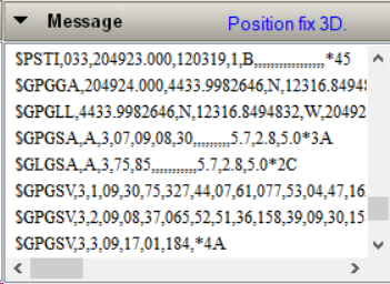
A 3D Position Fix in GNSS Viewer
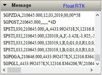
An RTK Float in GNSS Viewer indicates the serial port baud rate is correctly programmed
The above images show a GPS rover receiving RTK corrections correctly on a serial port at 57600 baud from the GPS base. The position starts as a 3D fix and eventually resolves to a Floating RTK measurement. Now, we are going to program the rover and base to communicate at 115200 baud so that they can be used with the Freewave radios!
Programming the Base
This step is relatively simple: connect to the base by setting the baud rate in GNSS viewer to 57600 and then click “Scan Port” in the lower left corner of viewer. If you don’t see the base in the viewer, it is either not connected properly to the computer or not at the baud rate that you selected.
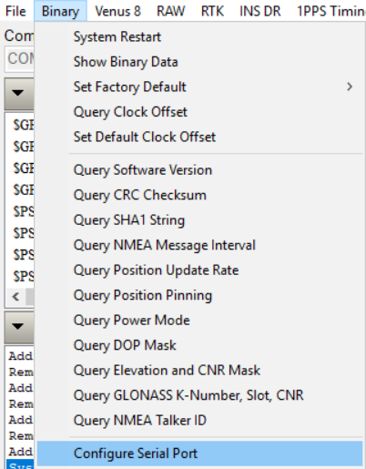
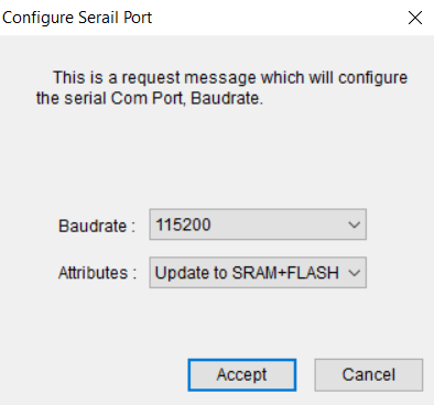
To set the RTK output baud rate, select “Configure Serial Port” from the “binary” dropdown menu. Set the baud rate to 115200 and update to SRAM and Flash.
Setting the base baud rate, 1
Setting the base baud rate, 2
Programming the Rover
Before setting the rover’s baud rate, we need to understand how the serial ports work. The each GPS has a master and slave UART. The slave UARThandles the RTK data and the master UART handles position calculation and resolution. The RTK data comes into the unit via the slave’s UART on (RX2) and is then processed and the NMEA (position) strings come out on the TX1 pin. So, to program the slave’s baud rate, we have to enter a passthru mode!
Click on the “RTK” dropdown menu, and then click “Enter Slave UART Pass Through (Master Only)” from the “RTK-Pass Through” option.
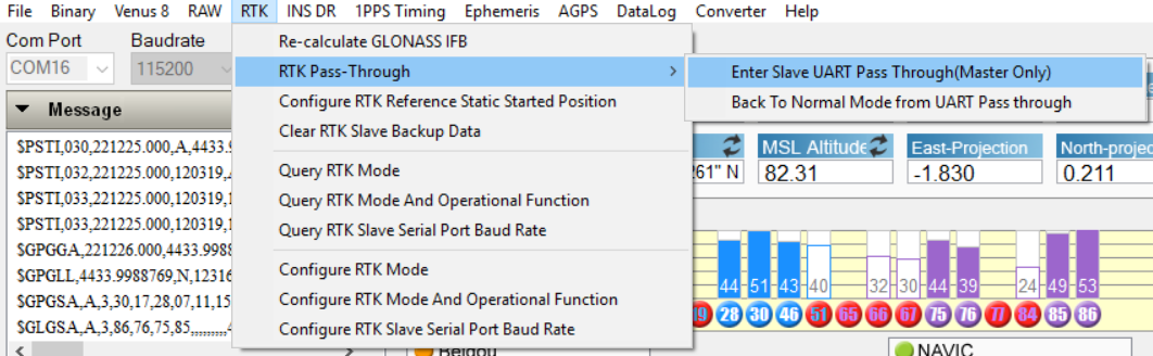
After using this command, the GNSS viewer should stop updating the position and new position data will no longer be coming in (visible in the serial window). Next, set the baud rate the same way as we did for the RTK base. Finally go back to normal mode (Menu option below “enter slave UART pass through). Connect the two GPS modules and wait for the rover to get an RTK Float and hopefully an RTK fix (depends on satellites in view).