
Author: Grayland Lunn
Now that we can send and receive data using the Freewave radios on passthru mode, it’s time to use them to send RTK data and get and RTK fix with a GPS. If you’re using this post as a guide for connecting the radios and haven’t yet sent data via the radio link, go back to the first configuration of the Z9-T DEVKIT blog post and follow the setup procedure listed there.
Terminology Used
Rover: The rover is the GPS unit used to read actual position measurements. It receives corrections from a “Base” GPS unit to resolve a very specific geo-spatial reading.
Base: The base is the GPS unit that has a stationary position and sends RTK corrections to the “rover.”
Gateway: This is the server radio in a network. Its serial RXD connects to the Base’s serial TX. There can only be one gateway in a network and any data received by the gateway’s serial RX transmitted to all the endpoints in the network.
Endpoint: This is the radio that receives all data transmitted by the gateway. With our application the endpoint’s are connected to the rovers in the network. The endpoint’s TXD connects to the GPS RX2.
Settings for GPS RTK Data
The Navspark S2525F8-GL-RTK is an RTK GPS module that is able to use corrections sent from another receiver to cerrect it’s readings and improve GPS spatial resolution from 3-5m to 1cm. Two GPS units are set up as “rover” and “base.” The base sends correction data to the rover on a UART serial connection, the rover then uses these corrections and outputs location strings in NMEA format on a separate UART.
Here are the settings for RTK communication:
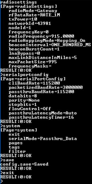
Freewave shell settings for the Gateway radio.
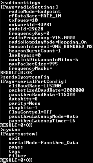
Freewave shell settings for the endpoint radio
Configuring hardware for transmission
After the radios have been configured, disconnect them from their power sources. On the gateway, move the 5 pin x 2 pin jumper block to the D9 TTL port setting. The D9 TTL connector is used for communication with the GPS unit. To connect the D9 port to the Navspark base, use female stacking row headers (a row of 4 and a row of 5) inserted into the D9 port and jumper cables connected to the Navspark’s RX1 and GND pins. The GPS GND connects to the Freewave GND (D9 TTL port, pin 5) and the GPS TX1 connects to the Freewave RXD (D9 TTL port, pin 3).
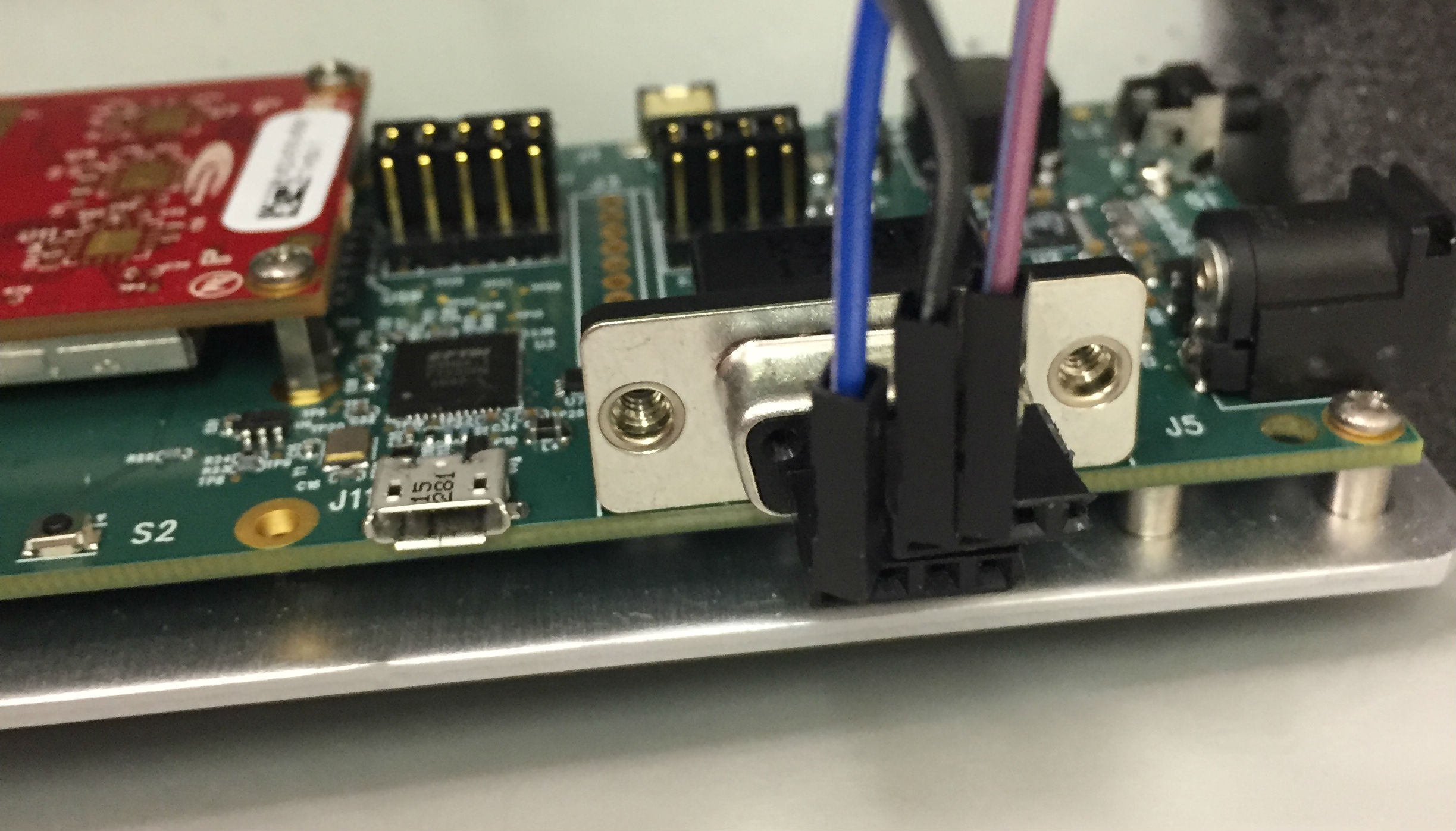
Female stacking row headers interfaced into D9 serial port
To verify that data is being read, sent, and received with the Freewave radios, power on the endpoint and connect it to an opened terminal. Check that the endpoint is communicating with the terminal by opening the Freewave shell. Check that system.serialmode=Passthru_Data, then save and exit the Freewave shell but leave the terminal open. Now that you’ve updated the settings for the radios’ serial protocol, check the Tera Term serial port settings and make sure that they are matching the settings the freewave SerialPortConfig showed. Specifically the baud rate is 115200 and flow control is off. Once you see the terminal filling with random characters coming in once every second with the settings as shown, the Freewave radios are properly programmed for this test.
Getting the RTK Fix
Once the endpoint is receiving the RTK data and the terminal is displaying this transmission, disconnect the radio from the computer and power. Change the endpoints 5 pin x 2 pin routing jumper to the TTL side so that the signals are routed to the D9 serial port.
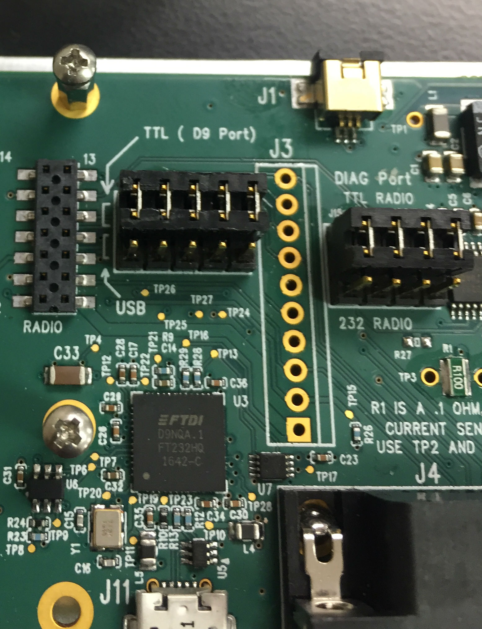
Routing Jumper Configuration
Next, connect the Navspark rover’s GND to the Freewave endpoint’s D9 GND (pin 9) and the Navspark RX2 to the Freewave endpoint’s TXD (pin 2). Power on the Navspark GPS by connecting the mini USB connector to your computer. Open up the GNSS Viewer to see the GPS position data in real time. Then power on the Freewave.
Within the GNSS viewer you should be able to see the GPS position measurement go from 3D position fix to differential GPS to RTK Float to RTK Fix within a few minutes. Once the position reading is RTK float you can be certain the Freewave radios are connected and working properly.
If you can’t get a RTK position, here are a few things to try:
- Make sure the base’s antenna has not been moved since being turned on. Just power cycle it to have the base resolve a new fixed location within a couple of minutes.
- Check that the GPS can get an RTK position reading with the hardwired serial connection shown in the Napspark Getting Started guide.
- Make sure that the freewave radios are configured properly.
- Program the GPS rover serial port baud rate to be 115200. Program the GPS base serial port baud rate to be 115200.