System for Testing RFID Tags’ Ability to Sense Humidity

Author: Brett Stoddard

Hello  Everyone! 

For the past few weeks, I’ve been further examining the RFID Dogbone Tags. This time I’m testing their capability as capacitive humidity sensors. This article describes the system I built to test them out.

Abstract and Objectives

This blog post describes a system to log data from multiple Smartrac Dogbone RFID moisture sensing tags in the air over the course of the day. The goal of this system is to log the Dogbone’s moisture sensor levels vs a DHT11 Humidity and Temperature sensor. After logging data for multiple day cycles, enough data should be present to tell if there is a relationship strong enough between the Dogbone’s measurements and the DHT11. Further testing would be warranted if such a relationship exists.

To measure multiple tags at once, this system incorporates a HyperRail prototype. The HyperRail’s details can be found distributed throughout this blog page on the OPEnS site.

Materials

Libraries

Description


Results

Over the weekend the system was run. It gathered some data, but not enough to make a sure prediction of whether the Dogbone tags can be used as humidity sensors. However, this is an example of what the code output should look like.

Values of RFID, Humidity, temp, EPC, time, f

What data should look like when opened in Excel

Known Issues

As of now, the SD card will only log data when the Arduino is plugged into both USB. This shouldn’t be necessary because it is already powered by Vin. This issue is probably a power supply limitation of my specific setup, however, I thought it was worth noting here.

Shield Sandwich for Dogbone Tags

By Brett Stoddard

Abstract

One problem that I’ve been having with burying the Smartrac Dogbone tags is that soil is that they break after some use. After taking a close look at some of the broken tags it appears that this is caused by the abrasive soil eventually cutting through the outer lamination of the Dogbone tags and then damaging the IC that controls the tag, causing them to become unresponsive. To counter this, I designed a two part protective enclosure for the tag that will hopefully protect them from damage. The design is outlined below:

Materials

Design

This “Dogbone Sandwich Shield” is made up of two identical 3-D printed parts. The sandwich ends were designed to be slightly larger than the Dogbone’s footprint with two tabs on the long ends. The tabs were placed like this to minimize interference with the moisture sensitive area of the tag which sits at its center. 

Assembling the product was a fairly simple process. First, the Dogbone tag was stickered onto one of the sandwich ends. Then a small amount of acetone was brushed onto all of the sandwich end’s tabs. They were then pressed together to create a sandwich with the Dogbone in the middle. The sandwich was then treated in an acetone air bath to seal the edges. After 20 seconds in the air bath, the part was removed and put in a vice under a small amount of even pressure to make it even until it hardened. It takes around a day to fully harden, but it is tough enough after an hour. Below is a picture of the final shield. 


Two built RFID sandwiches. One made of ABS plastic, the other made from HIPS

Results

The presence of the shield surrounding the Dogbone tag made it slightly less sensitive to moisture, however, the variance from readings with the shield was no greater than it was without them. Therefore, using the shield will not influence the accuracy of the sensor once, but it will require some re-calibration.

Thinking Ahead

Thinking ahead, creating shields like this one with varying thickness could allow for changing the sensitivity of the tags. Currently, without a shield, the tags read their lowest value before the soil has gotten completely saturated and are able to read soil that is more than completely dry. Adding a shield that is a certain depth should shift the reading range to be centered and allow the tags to read over a larger range of soil conditions than they currently do.

Files

STL file shield tag

Developing an altitude hold algorithm for a quadcopter

Author: Jonah Siekmann

For the past few months, the drone portion of the RFID moisture project has been focused on the altitude hold algorithm of the drone flight controller as a sort of first step towards autonomy.

Abstract

Currently, the user is responsible for throttle, pitch, roll and yaw – in theory, altitude hold would remove the need for the user to moderate throttle while GPS navigation would remove the need for the other three. The user would just need to flip a switch on the remote control, and the drone would use a sonar sensor to determine the altitude from the ground. The sonar is mounted on a gimbal so that regardless of the drone’s orientation, it is always pointing at the ground.

Materials & Description

We constructed a gimbal from two digital servos and used an MPU 6050 to get positional data. We also used an HC-SR04 sonar sensor and arduino to process the data. Initially, the sonar sensor was located directly underneath two propellors, which resulted in propwash interfering with the sensor receiving pings. This meant the flight controller could go for seconds without a single reading indicating its position relative to the ground – an extremely unsafe predicament. It could have crashed or flown dozens of meters into the air in the meantime.

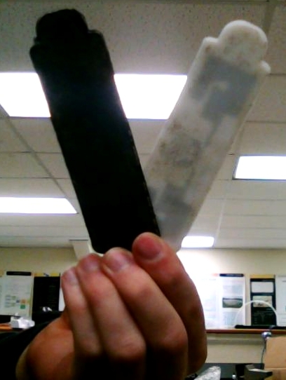
 Some online research revealed that the best place for a sonar sensor was in the exact center of the frame. So the drone’s battery, Arduino, and gimbal were removed and reassembled in a spot that allowed the gimbal to be in the center. The result looks like this:

This allowed for much more consistent readings. Afterward, the problem arose of using a PID controller that assumed a constant time interval to control drone altitude. Normally, a PID controller looks something like this.

  integral += error; //integrate errors by adding them together
  derivative = (error - prevError); //get derivative by finding difference
  prevError = error;
  output = KP * error + KI * integral + KD * derivative; //multiply by gains

And this worked fine for previous flight controllers that I’d written. However, this is because they used a constant loop time of exactly 4ms – meaning that the flight controller would poll sensors for new data exactly every 4ms.

However, in the case of a sonar sensor, the time it takes to get a reading depends on how far away an object is. If a drone is hovering 20 feet in the air, it can take around 40ms to get a ping back from the ground – an extremely long amount of time in computational terms. So instead, an interrupt subroutine was used as described in this instructable:

https://www.instructables.com/id/Asynchronously-Reading-the-HC-SR04-Sensor/

However, this meant that the time in between readings is not constant and can vary hugely. For a PID controller, this is a massive problem – say two readings are taken, the first at 3m and the second at 2m. If there is a one second difference between those readings, then they can be taken to mean that the drone is dropping at 1m/s and needs to be corrected immediately. If there is a ten second difference, it is only dropping at 0.1m/s and the correction should be a lot less forceful. However, the PID controller as above would consider both of these cases to be identical and react inappropriately.

Essentially, it’s necessary to take time into account when reading data from a sensor that does not provide readings at a constant rate. The resulting PID subroutine looks like this:

  int dt = micros() - timeOfLastExecution;
  timeOfLastExecution = micros();

  integral += error * dt; //multiply error by time interval since last reading
  derivative = (error - prevError)/dt; //divide rise over run - dY/dt
  prevError = error;
  output = KP * error + KI * integral + KD * derivative; //multiply by gains

Results

This steps described in this post allowed the altitude hold algorithm to be realized. Below is a video of a rough working version of the altitude hold algorithm – the PID values are not yet tuned. The throttle was not touched for the entirety of the following video after about 0:07 seconds – the only axes controlled were pitch and roll.

System for Calibrating Dogbone RFID Moisture Sensors using Decagon 5TM Conductivity Sensor and I2C Communication

Author: Brett Stoddard

Hello  Everyone! 

This last week I’ve been working on getting a system to log data that I will use to calibrate the Smartrac Dogbone RFID moisture sensing tags in soil

Abstract and Objectives

This blog post describes a system to log data that I will use to calibrate the Smartrac Dogbone RFID moisture sensing tags in soil using a Decagon 5TM moisture sensor. The goal of this system is to log both 5TM’s electric permittivity readings (ε) alongside Dogbone’s moisture sensor levels over a long period of time to make a relationship and eventually properly calibrate the Dogbone tags to the current industry standard, dielectric permittivity. 

Using a 2GB SD card, this system will be able to record 82 million data points, more than enough for our system (each data point takes up around 26 bytes and 2*230/(26) = 82*106 ). The period that the measurements are taken at can be changed easily, but is currently set at 10 minutes which gives a solid resolution but is still small enough to analyze easily. Theoretically, measurements could be taken with a minimum period of 5 seconds. The logged data points will be saved as a CSV file because those can be read by Excel which will make analyzing data fairly trivial. 

Materials

Libraries

Description

After encountering a few problems, the system that I settled on was two Arduinos that would communicate over I2C. I was forced to do this because the “SDI Library” that is needed to communicate with the 5TM soil sensor I was using is incompatible with the “SoftwareSerial” that was critical for debugging and testing the code.

I2C communication was originally developed for and is usually used for multiple chips on the same embedded electronic system to communicate over the same bus. It’s useful for when tasks need to be split between multiple Arduinos. I2C is implemented in Arduino using the Wire library. For this situation, the slave Arduino was the one reading data from the TM5 sensor. The nice thing about I2C is that it is relatively trivial to add additional sensors to any sensors to a setup in case we want to make multiple readings at the same time. The code for implementing this setup was written by following this tutorial

One Arduino was set as a slave and read the data from the 5TM sensor. I followed Chet’s Decagon 5TM sensor guide to set this up. The master Arduino had the GPS logger, and RFID reader shields on it to record the values. The RFID reader shield uses pins 2 and 3; the GPS SD logger pins 13, SCL, and SCA; and I2C pins GND, A4 and A5 on the master Arduino. The 5TM sensor used pins 6, 5V, and GND; and I2C pins GND, A4 and A5 on the slave Arduino. The hardware diagram shown below illustrates this.


calibrator-diagram

The code for this system will be posted in the examples folder of my RFID Github library under the title “Calibrator example”.

Results

Last night, the first data set was collected using this setup over the course of 16 hours. Below is the graph (made in Excel) that shows the Dogbone moisture values (units not named) vs the 5TM conductivity measurements (dielectric permittivity, ε). There was a recorded R^2 value of .75 which means there was a moderately high correlation between the two. As one can see from the graph, over time the 5TM’s electron permittivity decreased slowly as the soil slowly dried out. Longer-term tests where the soil has time to go from saturated to dry will be key for properly calibrating the Dogbone tags to the current industry standard, dielectric permittivity.


The x-axis has units of number of 10 minute intervals

The x-axis has units of number of 10 minute intervals

Toward Comparing RFID Moisture Performance with Industry Standards: Decagon

Author: Chet Udell


Abstract:

Our previous experiments have shown the RFID moisture sensor tags are in-fact reading gradual changes in soil moisture content. The next step is to compare the performance, consistency, and resolution of these tags to industry standard equipment to see how it measures up using Decagon Devices soil moisture sensors. In this post, Chet gets a 5TM Soil Moisture and Temperature Sensor chatting directly with an Arduino to deploy in experiments, and eventually integrate into the battery of available Internet of Ag sensors.

Objective:

In order to compare the performance, consistency, and resolution of the RFID moisture tags, we hope to conduct some comparative experiments between these and Decagon’s popular soil moisture sensors, namely the 5TM (soil moisture + temp). Decagon’s readers can be pricey and we want to use these sensors in very specific ways, so the objective here is to get the sensors talking directly with an Arduino. The following method can be used to read any Decagon soil moisture sensor over the SDI-12 serial protocol. For more info on SDI-12, visit here. Why the 5TM? The 5TM determines volumetric water content (VWC) by measuring the dielectric constant of the soil (or other media) using capacitance/frequency domain technology. Signal filtering minimizes salinity and textural effects, making the 5TM accurate in most soils and soilless media. Factory calibrations are included for mineral soils, potting soils, rockwool, and perlite. – from http://www.decagon.com/en/soils/volumetric-water-content-sensors/5tm-vwc-temp/

Materials and Methods

What you’ll need:

  1. Download the above library, unzip. Rename the file “SDISerial” and place in the folder: <Arduinno root folder> / libraries
  2. Following the instructions on the library GitHub page (image included here), clip the 1/8 inch jack off of the Decagon sensor (ouch), strip off the leads to reveal a white, red, and “shield” wires. Solder each wire to a 0.1in pitch male header to use in a breadboard.
  3. Connect your arduino up to a breadboard and the 5TM lines White => 5V, Red => DATA_PIN, Shield => GND
  4. DATA_PIN MUST be connected to a pin with a hardware interrupt (for Uno, P2 or P3).
  5. Use the below code and you’ll get soil moisture and temp readings (in Celsius).
  6. Your output will look like the below screen print

Results

As you’ll see from the below code and printout, the SDISerial library enables the arduino to send commands to the 5TM to procure data. Now, we can employ these sensors in almost any Arduino application! This is done by creating an instance of SDISerial connection(DATA_PIN); and then starting the serial connection using connection.begin();

You can then use the function connection.sdi_query() to send various commands to the 5TM. This function uses 2 parameters: (command, timeout-duration)

connection.sdi_query(“?M!”,1000); This sends a message to query the first device on the bus – which in use seems to refresh the values of the sensor readings, but does not return the sensor reading itself. Instead, it returns a message that tells you the maximum wait before the measurement is ready. timeout set for one second.

connection.sdi_query(“?I!”,1000); will get sensor info and timeout if no response in 1 second

connection.sdi_query(“?D0!”,1000); will query the 5TM for sensor data


Hookup on a Mega, similar to the Uno


Resulting output
/*
Tested on UNO R3.
Sketch was built with Arduino 1.6.12
Dependency: Joran Beasley SDISerial Library
Accessed May 26, 2017 here:
https://github.com/joranbeasley/SDISerial

download and rename folder "SDISerial" and place in  "<ARDUINO_ROOT>/libraries"

Tested with the with the 5TM Soil Moisture and Temp Sensor:
http://www.decagon.com/en/soils/volumetric-water-content-sensors/5tm-vwc-temp/

Hook-up:
the WHITE wire goed to 5V. however you could also connect it to a pin and drive power only when you wanted it
the RED wire is the DATA_PIN. - you must hook it up to a pin that can process interrupts (see link below)  
the remaining "shield" wire must be connected to ground
*/

#include <SDISerial.h>
#include <string.h>
#define DATA_PIN 2
SDISerial connection(DATA_PIN);
char output_buffer[125]; // just for uart prints
char tmp_buffer[4];
char* resp; // Pointer to response char

//initialize variables
void setup(){
      connection.begin();
      Serial.begin(9600);//so we can print to standard uart
      //small delay to let the sensor do its startup stuff
      delay(3000);//3 seconds should be more than enough
      char* sensor_info = connection.sdi_query("?I!",1000); // get sensor info
      //print to uart
      sprintf(output_buffer,"Sensor Info: %s",sensor_info?sensor_info:"No Response");
      Serial.println(output_buffer);
}

//main loop
void loop(){

   //print to uart
    Serial.println("Begin Command: ?M!");   
    //send measurement query (M) to the first device on our bus
    resp = connection.sdi_query("?M!",1000);//1 second timeout
    //this really just returns a message that tells you the maximum wait before the measurement is ready
    
    sprintf(output_buffer,"RECV: %s",resp?resp:"No Response Recieved!!");
    Serial.println(output_buffer);
    delay(1000);//sleep for 1 seconds before the next command
    
    //print to uart
    Serial.println("Begin Command: ?D0!");
    resp = connection.sdi_query("?D0!",1000);//1 second timeout
    
    sprintf(output_buffer,"RECV: %s",resp?resp:"No Response Recieved!!");
    Serial.println(output_buffer);
    delay(3000);//sleep for 10 seconds before the next read
  
}

Moisture Reader Update 3

Author: Brett Stoddard

Hi everyone, it’s been a while since the last update with the moisture sensor and a lot of progress has been made in that time. Progress has been made with confirming moisture readings and on the code side of things.

After a few more rounds of testing I have confirmed that the tags, for sure, can be used to measure a range of moisture levels. The test involved dropping different volumes of water onto the edge of a tag’s tail. The tail would soak some of that water up and onto the moisture sensitive part of the tag. The tails were about an inch long and increments of 25mL of water was dripped onto them using a precision eyedropper. The data (TABLE 1) showed a definite positive correlation which is good news. I also did a few trials on really wet and really dry soil and the tags were able to tell the difference between a desert and a swamp, although a more accurate of testing tags in soil was needed–which is where the next development comes into play.


TABLE 1. Table of tag measurements given a certian amount of water on the edge of the tail of a tag and a certian amount of time for the water to work its way up the tag.


Since the last post, I have gotten the RFID reader shield and the GPS logger shield to work together. I have added a polished example code bit onto the GitHub library. Available here, it records the average value of the RFID tag after 100 measurements then records measurement from a YL-69+YL-38 moisture sensor. The plan with this reader is to eventually use it to calibrate the values that we’re currently receiving off of the RFID tags (0 for wet, 20 for dry). This will involve setting the YL probe and RFID tag onto the same soil sample and letting it sit there for a few days and take measurements periodically as the soil drys. After we get this data we will be able to tell how well the RFID tags will work for measuring soil moisture.

I have also gone through and updated a little bit of the other example codes to make them work better.

Cheers, Brett Stoddard

Drone build completed

Author: Jonah Siekmann

It’s been a while since we updated this blog on the drone build progress, but today the last part came in and the drone is officially flying! We still have to mount the RFID/GPS stack, so it’s not autonomous, but it’s flying very smoothly.

For the drone, we used:

CC3D Flight Controller

750kv 28-30 motors

30A SimonK ESCs

11″ propellors

5000mAh 4s 25c battery

Flysky T6 transmitter/receiver

S500 frame

Here is a short video showing part of its maiden flight:

Also, you may recall in the last drone update, we documented an issue where the Arduino Uno microcontroller would shut off mid-flight – this was because of a faulty UBEC that wasn’t supplying a steady 5v, forcing the Arduino’s internal regulator to work overtime and thus overheating. Replacing the UBEC solved the issue. 

Now, we just have to program the autonomous navigation portion of the drone and mount the Arduino/RFID/GPS stack. 

RFID Sensor Update 2

Author: Brett Stoddard

Hi everyone, this week has been an exciting one for the world of OPEnS RFID moisture sensing. Since the update, we have found ways to make the sensors even more reliable and sensitive. Two updates have allowed for this development.

The first major modification came when “tails” were added to the RFID tag. These tails are made out of a paperlike material that’s designed to suck up and hold and moisture it comes into contact with. The more moisture it touches, the more water it sucks up thanks to capillary action. Tails can be positioned on the sensor to hold the liquid in the most moisture sensitive area of the tag to maximize the accuracy of readings. Sure enough, as soon as we started gathering data with the tails attached the reliability of our measurements improved by a lot. An image from one of Smart Trac’s technical documents showcases the tail below. All future testing will be done using these tags.


Image of a tail attached to an RFID tag


The second change was implemented on the software side of things. Before this week the sensor value was only read once and then outputted. The new code took 100 readings and then outputted the mean value. By using this method, more reliable and accurate readings were made. These new readings improved consistency across all of the tags for sensing extremely wet, extremely dry, and moist tail conditions. In the future, we will examine the exact distribution of the readings to determine the minimum number of readings that are needed to get a value with 80-90% certainty. The example code can be seen in this folder of the RFID library. This code is not yet optimized.

RFID Sensor Update

Author: Brett Stoddard

Hello all, it’s been a while since the last sensor status but from now on I’ll be working to increase my posting frequency.

Since the last update, many things have been happening on the sensor end. First, the OPEnS lab bought a new RFID module to interface with the Arduino UNO and have semi-officially scrapped the LinkSprite LSID-0702 reader. From here on out, we will be using the SparkFun Simultaneous RFID Reader – M6E Nano shield. I was really excited to get working with this reader because it’s documentation is a lot more readable and through than the other modules I’ve worked with.

That documentation included a SparkFun proprietary library especially made for use with the Arduino UNO. I forked this library on GitHub and have been adding to it a few functions specifically geared towards reading the moisture information from Smart Trac RFID tags. For the most part, these functions seem to work! The original SparkFun library is available by clicking here. The OPEnS lab version of it that I have and will be adding to can be found by clicking here.

The rest of this blog post will be dedicated to the results of tests run to prove that the retrieved values are dependent on the actual moisture of the chips. “Wet” tags were held under a stream of moving water in the sink for five to ten seconds. “Dry” tags are either tags that were never wet or ones that were set out to dry for a few days. 

FIGURE 1. Raw, unprepared data from the serial port of the Arduino UNO when example code from the library is run.

This data was gathered by modifying a read EPC byte command to read a different registry. What that means is that the data is unparced and looks gross. The important thing from this data is that the sensor code was reading a different number when it was wetted. When dry the tag had a value of either 12 or 14 HEX (18 or 20 decimal). Then when that same tag was run under the sink it read a value of 0C or 0C HEX (12 or 13 decimal). Being able to tell the difference between really wet and completely dry is a large step forward for this project and this data, if consistent, will allow us to do just that. However, as always, more testing will be needed to make this process robust enough for use in the field. 

Asynchronously Reading a Sonar Distance Sensor

Author: Jonah Siekmann

To get the quadcopter to fly at a set altitude above crops, we need to use a distance sensor (or more likely, a combination of distance sensors). We’re going to use a sonar distance sensor for at least part of the altitude calculation. However, the speed of sound is pretty slow. In the time it takes the sensor to send a ping and receive the echo, dozens of milliseconds could have passed. So we need to read it asynchronously. This turned out to be a little trickier than I first thought, so I made an instructable on it. You can read it here:

https://www.instructables.com/id/Asynchronously-Reading-the-HC-SR04-Sensor/