Power Pulse Controllers Done!

Abstract: The Power Pulse Controller project has come to a conclusion. All three PPC’s have been made! Final testing is the next step to get them ready for use. 

Methods: N/A

Results: 

The following image displays a finished Power Pulse Controller. We sold one to Columbia University and have two in stock. I will get in contact with Jim Wagner to verify all the connections and test the units to make sure that they are ready.


Fully assembled Power Pulse ControllerFully assembled Power Pulse Controller

Fully assembled Power Pulse Controller


20171101_100329.jpg20171101_100329.jpg

Power Pulse Controllers

Abstract:

I have been putting together three power pulse controllers. One has already been sent out, but two more are in production. Here is a quick overview of the system specs and parts. 

Methods:

I used Fusion360 for the modeling of the PPC and to create the 2D drawings so that other people can create it more easily. 

Results:

Here is the model of the finished model on which everything was based off :

The 2D drawings (link above) contain the layout of the components on the backboard and the locations of the holes made for the components that go on outside of the enclosure. There are some extra components that are not modeled in the CAD that come with the enclosure. These are not modeled because we were not the ones who put them on there; our pieces do not interfere with these pieces.

Here is a picture of the extra pieces that come with the enclosure:


IMG_2927.jpgIMG_2927.jpg

Here are other pictures of the other two Power Pulse Controllers being built:


3D Printing a Culvert Entrance

Abstract: 

I’ve been working with Desiree D. Tullos to create a 3D printed culvert entrance. The designs are done and are about to be printed. These will help illustrate the flow of water in a real system. The designs were created to simulate an efficient and inefficient culvert. 

Objective:

To simulate the inefficiency and efficiency of water flow in a real culvert using 3D printed culvert entrances and acrylic tubing for the pathway of the water. 

Materials and Methods: 

Desiree’s team sketched the design in 2D and then passed the specifications to me. I then designed the 3D model, in Fusion360, from the 2d design. We will print these on the Fusion3-f400. Here are the designs: 


Results: 

I still need to print them, but I did test print the entrance of the piece and it fits well with the acrylic tubing. Here are some pictures of the print:


Acrylic Tubing with o-ring Acrylic Tubing with o-ring 

Acrylic Tubing with o-ring 


3D printed entrance on acrylic 3D printed entrance on acrylic 

3D printed entrance on acrylic 

Em50G Data Loss Solution

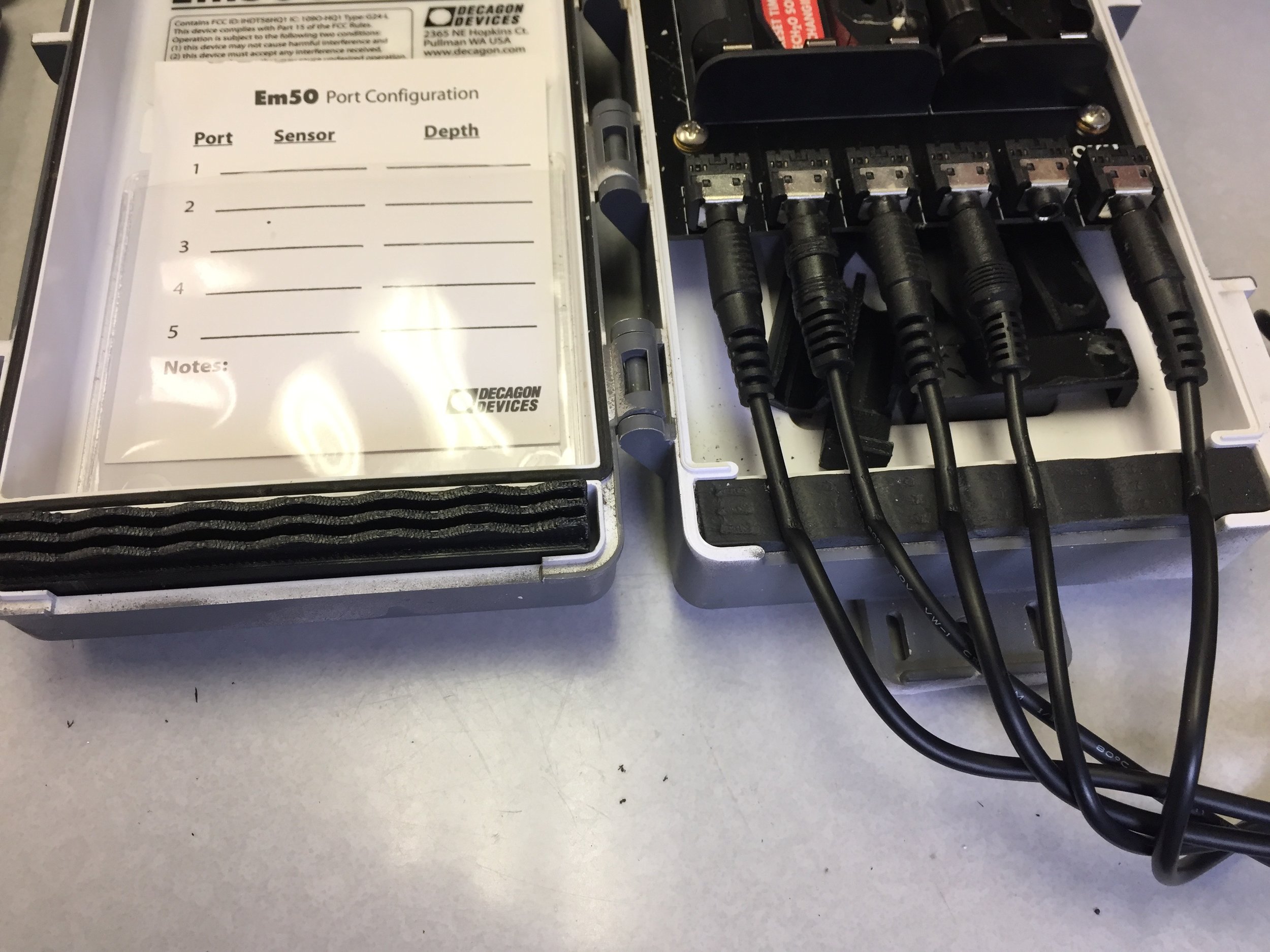
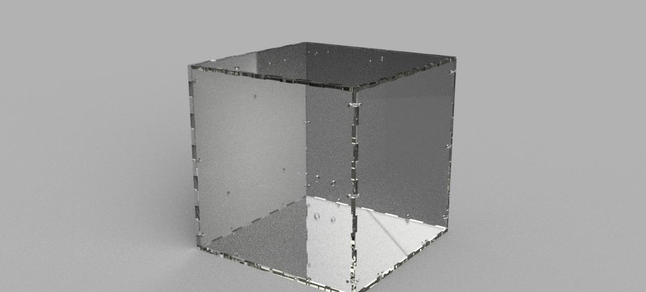
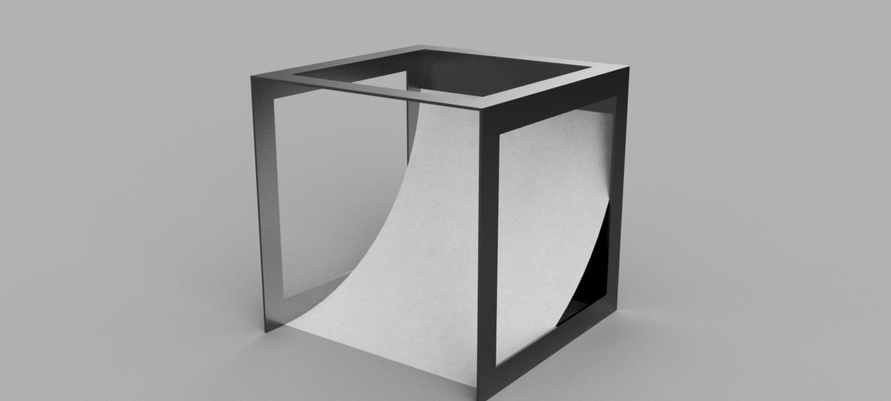
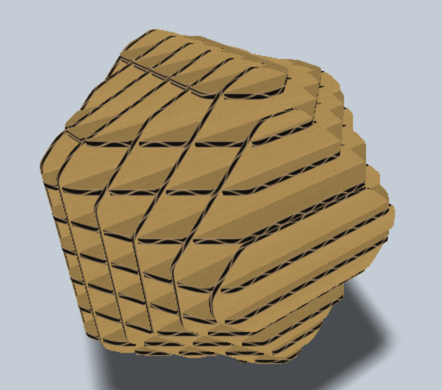
Losing data while performing field test is very inconvenient. The sensor cables connected to this data logger come out very easily and this causes data loss. I made a small clip that locks on the cable and rests on the sensor socket. This will prevent the wire from coming out. Here is the 3D model of the piece: 

Gripv13 By Manuel Lopez Modelo »

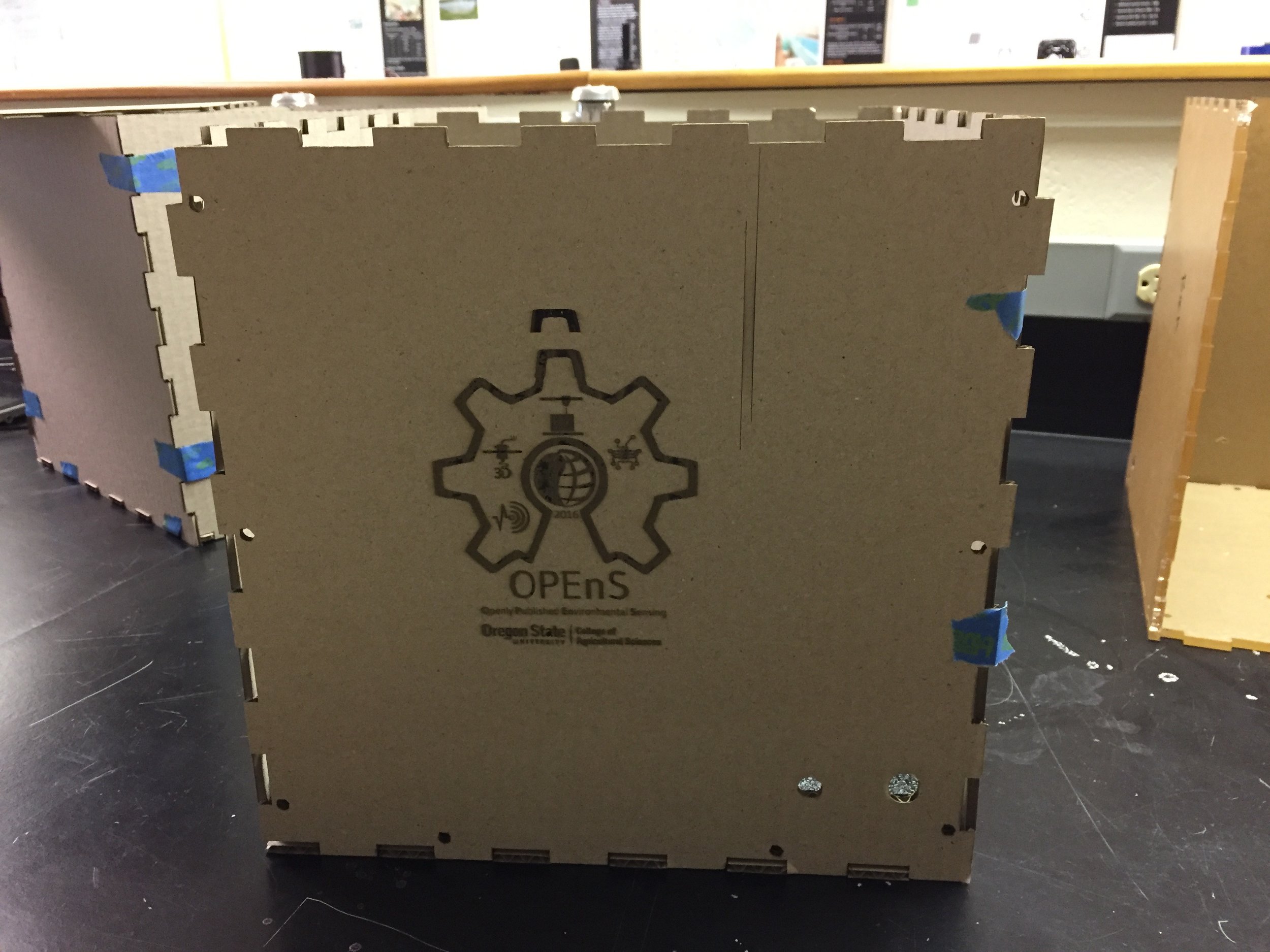
This grip will fit on most sensor tips. It is strong enough to keep clamp on the sensors but flexible to accommodate bigger sensor tips. Here is the actual piece on the Em50G. 


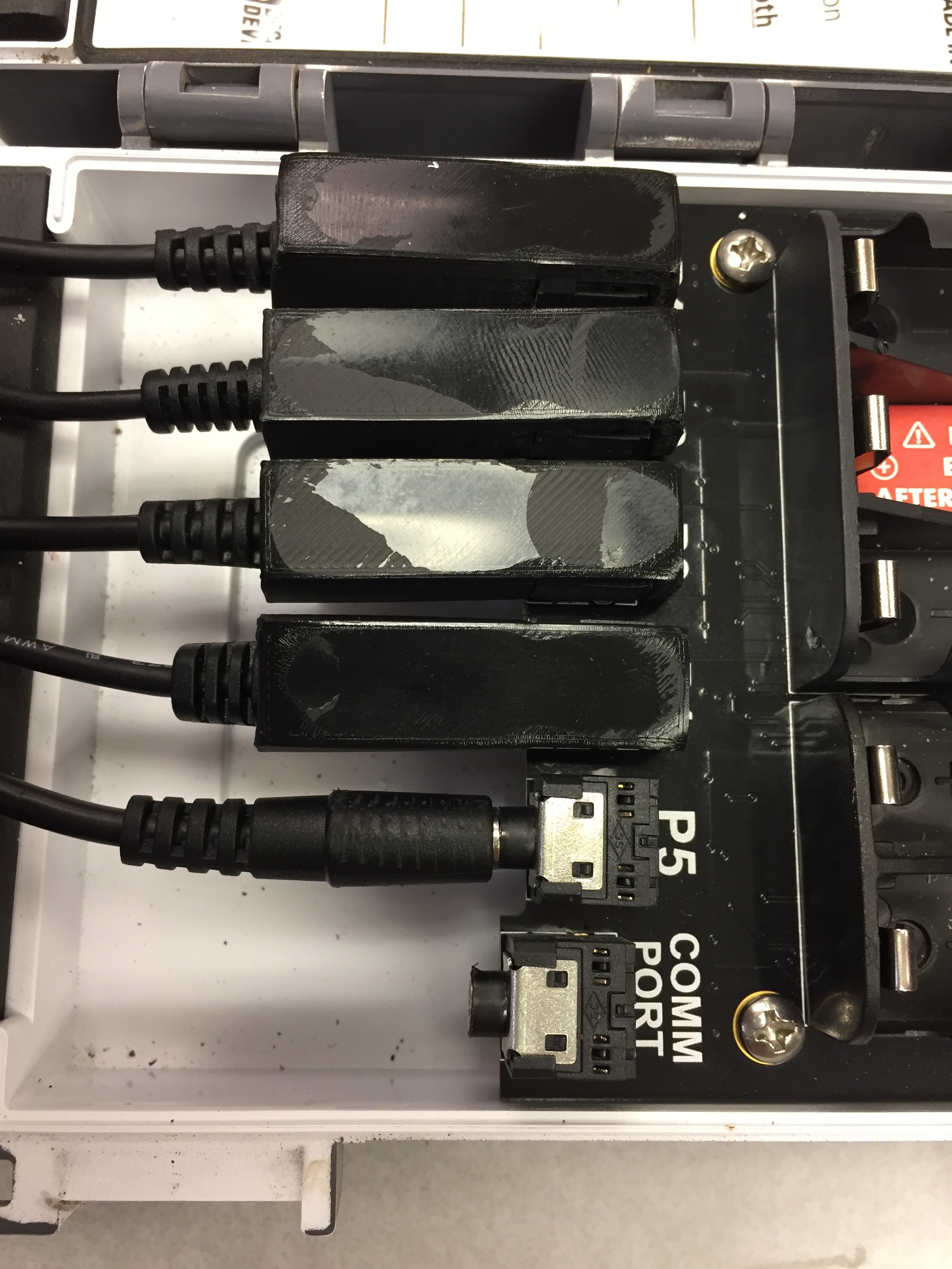
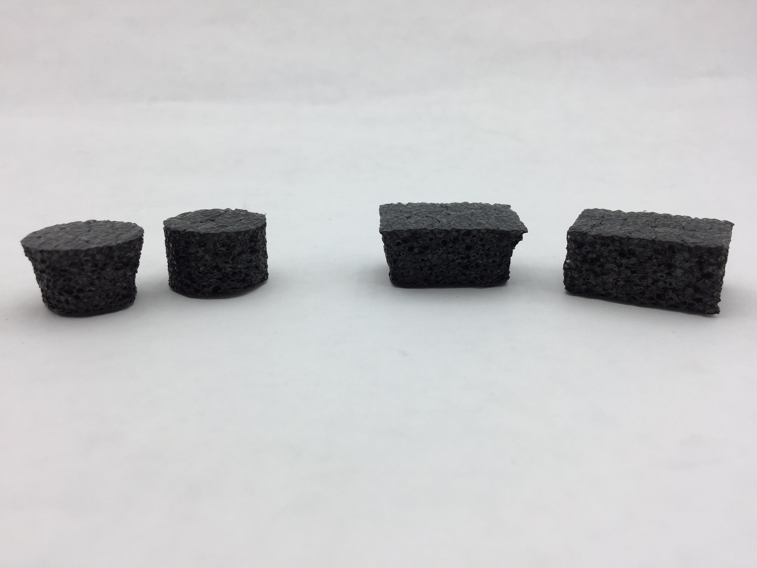
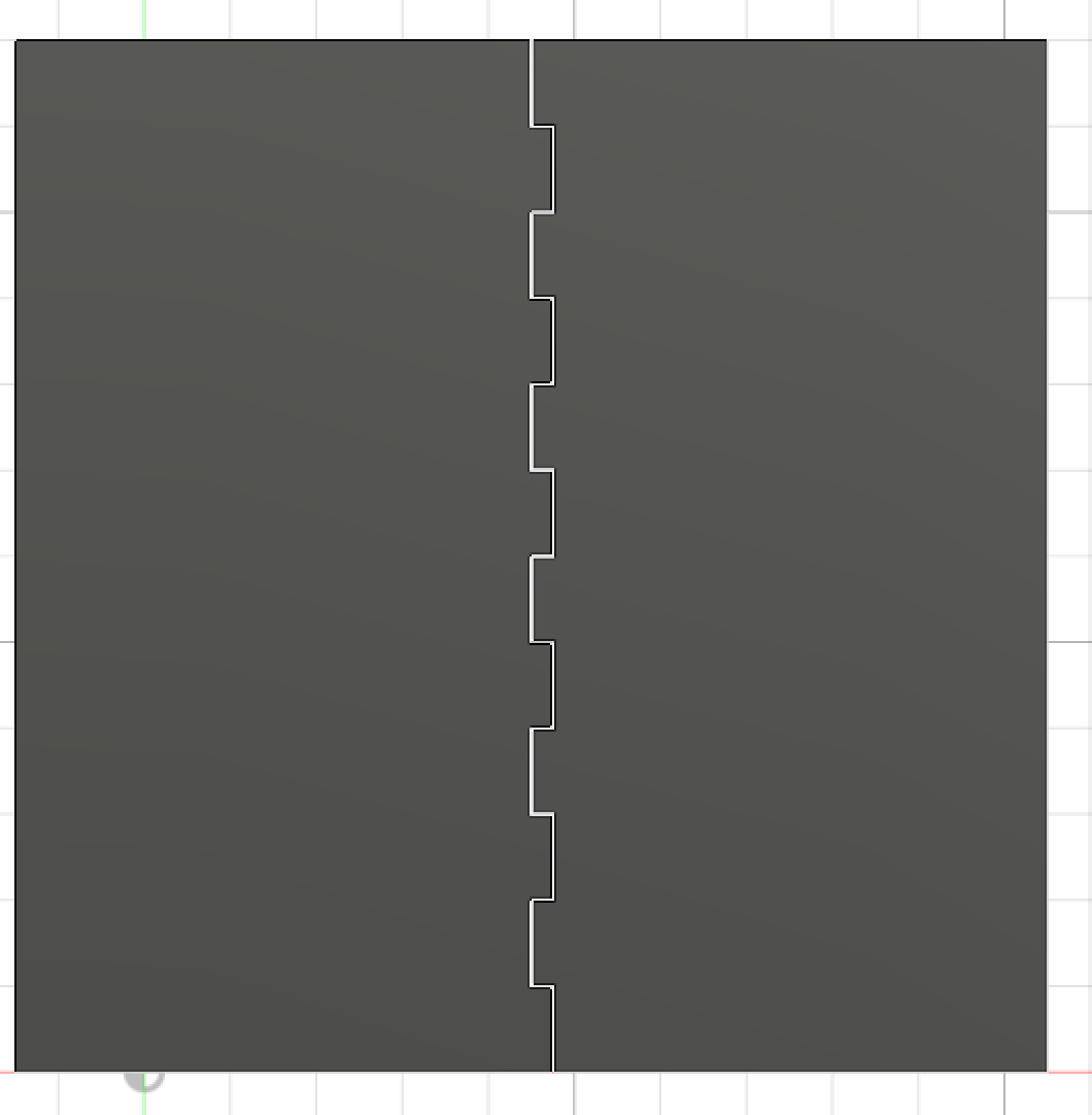
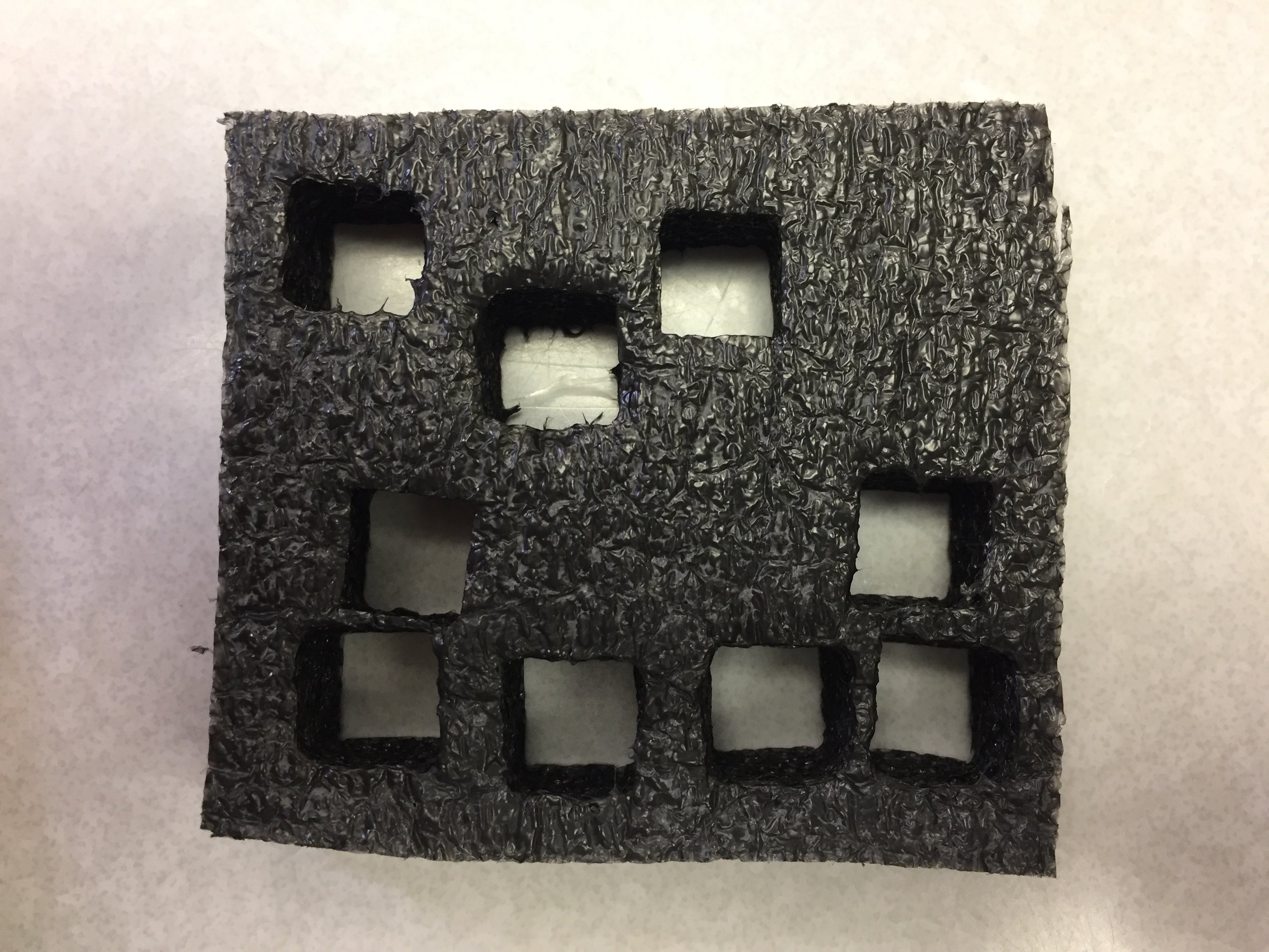
One concern with this solution is that the pieces might get lost since they are individual grips. The other concern is that while placing or removing the piece, the board might get damaged. Here is another solution that was proposed:


squeezev1 By Manuel Lopez Modelo »

This solution provides a more compact design because it’s only one piece. This design has a strong grip on the cable by pressing it against the foam. Here is are images of the actual piece. This design takes a little more effort to put in because you have to press the top really hard to get the sidelocks to get in place. 


New Laser Cutter Lens

The laser cutter came with another lens that we were totally unaware of its existence. Why would such expensive machine be missing one of its main parts? Looking through an accessories box of the laser cutter, I came across a little box that contained something wrapped in white paper- it was the other lens! The lens that we were using would only cut when it was in the metal-cutting position, even though we were not cutting metals. This new lens can cut in the non-metal and metal positions. 

New lens 

The very first thing that I tested  was if it could cut in the non-metal-cutting position. After that, I proceeded to test cardboard, plexiglass, and foam.When cutting foam we were getting beveled cuts. This was the main reason we considered buying to new lens to get better cuts. 

 Circle and rectangle test cuts with new lens. Of each set, the left pieces were cut with the old lens and right pieces with new     lens.

We can observe that the new lens can cut straight down the foam without creating a bevel. This is exactly the type of quality we need and expected from such a laser cutter. With our old lens it was really hard trying to get a straight cut; we got pretty close but nothing compared to this new lens.

Rube Goldberg Project Box

Making this box is not as simple as I initially thought. One of the most time-consuming parts of this box is making the finger joints. After making the finger joints the rest of the process was very smooth. 


CAD rendering of the box in acrylicCAD rendering of the box in acrylic

CAD rendering of the box in acrylic


Finger joint designFinger joint design

Finger joint design

The CAD was the first thing that was done and then DXF files were exported to the laser cutter. The first prototype of the box was made out of cardboard to make sure all of the sides would fit perfectly- not too wiggly and not too tight. 

The DXF files are the surfaces sketches of each of the faces of the box. These files are the ones that are processed into the commands that the laser cutter uses to position the laser. Having the CAD finished makes it easy to produce these files because we just pull them off the faces of our designs. 


Cardboard prototype 

We also did our first tests etching on cardboard. The OPEnS logo was the design that we used for our testing and it came out very well. 

First cardboard etching test 

Making Photo Booth for OPEnS Lab Projects

At the OPEnS lab we prototype many projects and need to document them. Pictures are essential to our reports and publications. In order to have the best quality pictures we decided to make a photo booth. Here is the CAD of our booth. 

First version of CAD

This photo booth is a light box, a tool to take professional looking photos. Our is a  DIY version of the ones we could buy. The idea is to have all of the openings covered with tissue paper and a light source on each side of the box. The paper will serve as a filter, giving the object inside an even lighting. Here is an example:

To take the CAD into the laser cutter I converted separate sides of the box into DXF files. These files are then processed by the laser cutter software and then loaded to the laser cutter. Here is what our photo booth looks like so far:

Some materials are still needed but it is almost done. 

Testing foam on Laser Cutter & Making Foam Inserts for Tools

The foam finally arrived and we have started to experiment with it. I cut various small 10 x 10 mm squares at different power levels, speeds and heights to determine our best settings. The settings that I observed were cutting the best: Power 17, Speed 23 and Height 3315.9mm. 


Sample cuts on foam 

After doing some testing I intended to  cut the foam inserts for the drawers. When loading the DXF file from Fusion360 on to MetalCut, the file appeared to be changed. There were some extra lines that were not supposed to be there. After analyzing the MetalCut file, I noticed that the program was making some discontinuities in the design outlines and created lines towards the center to compensate for it. I believe it was doing this because the file had some sharp edges and I think it doesn’t precess these edges very well. 

The Fusion360 design is being fixed. Only some pieces seemed to be affected by these sharp edges. After all the changes have been made, the cutting process should go smoothly. 

Using the Laser Cutter to Make a 3D Model

We took a 3D model of an Icosahedron and used 123D Make to create a 3D-laser cutter version. 

CAD Model

3D Model

We can now show demonstrate one of the uses for the laser cutter. This could be useful when someone needs to make a 3D model of a topographic map. This is also considerably faster than 3D printing this piece. 

Isotopic Sampler Bag Cap

A custom bag cap was necessary to function as a sealed connection between the aluminum foil bag and the fitting on the copper tube that attaches to the checkvalve. The dimensions of the bag’s mouth were measured with calipers and a first prototype was designed based on two pieces: an inner piece that presses against the end of the mouth with an o-ring and that can be tapped to fit to a 1/8 NPT fitting, and an outer piece that screws onto the mouth and forces the inner piece to seal (see picture 2).

The first prototype worked well and was lightly modified over time. Most of the caps were printed in HIPS as we were out of ABS at the time, but both ABS and HIPS print well.