Abstract:
LoRa is a Low Power Wide Area Network (LPWAN) hardware set for creating long range (2km to 10s of kilometers) star or star-of-star networks. OPEnS Lab is evaluating LoRa for on of it’s 4 Internet of Ag communication options (others being close-range RF (100m), WiFi, and GSM).
In this blog, one of our URSA Engage research students (Marissa K) got the LoRa radios up and running using this Adafruit tutorial. Below, she will detail what she had to do and modify to get this working with the RFM96W 433MHz breakout board – along with accompanying example code. These cost only $20.


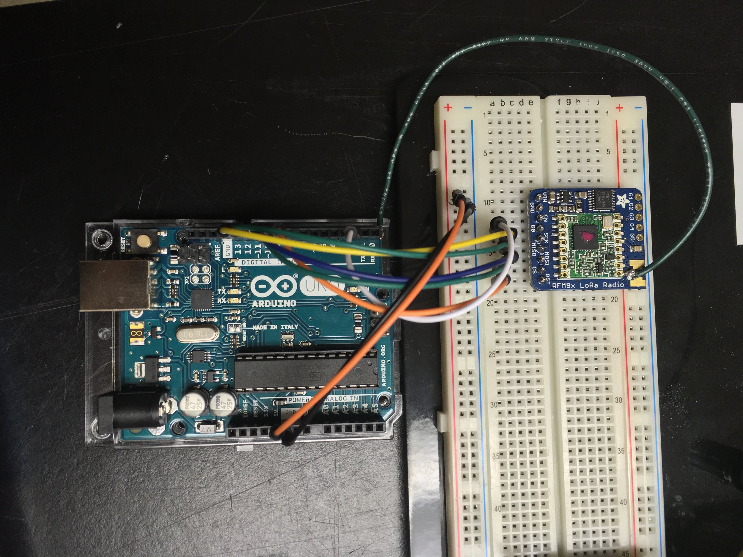
Arduino Uno connected to Adafruit’s LoRa RFM9x Radio Transceiver Module
Wiring:
Here’s the setup pictured above:
LORA Arduino Uno
Vin —————– 5V
GND ————— GND
GO (IRQ) ——— 2
SCK —————- D13
MISO ————– D12
MOSI ————– D11
CS —————— D10
RST —————- D9
GND ————— GND
Antenna connection – soldered a 6.5 inch wire (green) that corresponds to a frequency of 433 MHz
Note: The Arduino Uno is capable of supplying either 5V or 3.3V. For this project I went with the 5V supply since additional components used for collecting data from the surrounding environment will require a higher voltage and the LoRa pins use level shifting circuitry to safely power the chip with 3.3V-6V of direct current. With level shifting circuitry the MOSI on the LoRa radio operates on a 3.3V logic level while sensors connected to the power rails on the breadboard are powered with 5V.


LoRa Radio breakouts communicating; LED attached to designated “Receiver” LoRa Module
Code:
The source code used to program the LoRa radio’s to receive and transmit data came from the Adafruit website and AirSpayce’s Radiohead Library. In the Arduino IDE, the radio frequency was changed from 915.0 to 433.0 MHz. Here are the links for the code I used to program the transmitter and there receiver.
Serial Output:
Once the transmitter Arduino was programmed and powered, it initialized and began sending signals awaiting a response from another radio unit on the same frequency. If no response was found, then the following output would appear on the serial monitor:


Transmitter radio without a recepient
Once the receiver Arduino was programmed and powered the two began sending and receiving packets of information – in this case a simple message, RSSI signal strength, and a count incrementing after each successful exchange:


Communication between transmitter and receiver LoRa Radios; output printed to the serial monitor in Arduino IDE.
Now that the two LoRa radios can communicate we should be able to transmit raw data from one radio to another. The next step is to attach a sensor to the transmitter Arduino that collects such data in real time. Over the next few days I will be using Maxbotix’s XL-MaxSonar-EZ sensor to collect data and transmit that data to the receiver. The MB1220 sensor that I will be using detects objects within 15ft from the front of the sensor and outputs the distance away in inches when connected to the analog pin A0 on the Arduino and the breadboard’s ground and power rail supplying 5V.
Here is the data sheet for the MB1220 as well as the code used to test MB1220.


Maxbotix’s XL-MaxSonar-EZ sensor MB1220 with wires connected to Ground, Vcc, and Pin3 (Analog output).
– Marissa Kwon Undergraduate Student Researcher
