
This project is intended to be a mount for a hyperspectral camera. The interesting thing about this project is that the mount has to be able rotate and tilt up and down. The spinning and tilting will be determined by the user of the camera. Here I will post pictures of the CAD renderings and explain how they all go together.
CAD model of pole mount
This first image is the model of the first design. This mount is composed of four printed pieces: motor mount, shaft rest, and the shaft( motor coupler). the shaft is made out of two printed pieces that are then screwed together.
This 3D model is the shaft base/rest. The base has four ball bearings on which the shaft will be resting on. Theses ball bearings will allow for a smooth rotation of the camera. If these were not to be there, the shaft would be resting on plastic and the would potentially have a rough rotation. The hexagons that extrude from the sides are the locations of the ball bearings. This base will be the connecting piece between the shaft and motor mount.
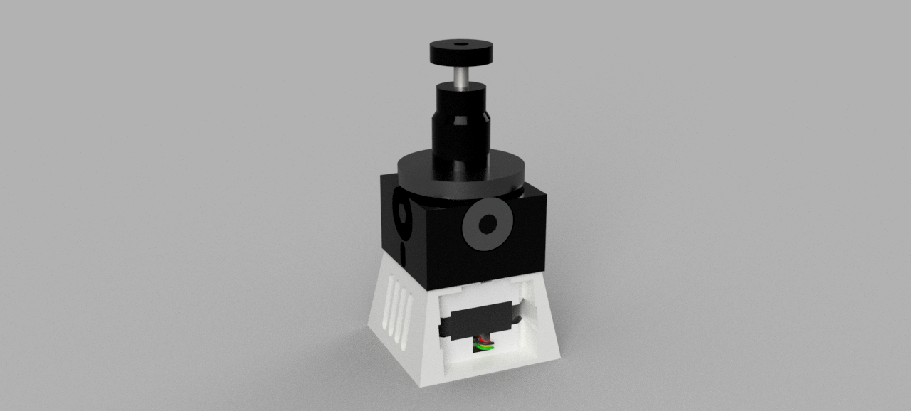
This 3D model is the motor housing. It is a pretty straightforward design. This model will house the motor and connect to the base that will be connected to the pole. It has slots that will allow airflow through the piece and keep the motor from overheating.
These two models are the shaft/ motor coupler. The top model is the piece that attaches to the 360 swivel and the bottom model screws on. This is the piece that rests on the four ball bearings and will be spinning.
I will now be printing the pieces and verifying that they all fit how they should be. Most of this design will be used for the other project. This other project will also be for the hyperspectral camera, but this design will have rails instead of a pole.