

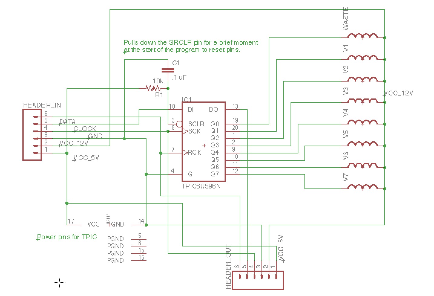
I’ve completed two schematics for this project. The first is the base unit schematic (above). This is the main unit we will develop first. The schematic includes 8 valves (shown as inductors on the schematic) and one TPIC power shift register for controlling them. 6 lines are connected to a header: 5V, 12V, GND, SCK, DATA, and RCK. Because the base unit will have 24-31 bags for sampling, rather than 8, we will be using 4 TPICs in series on a single board to control a corresponding number of valves. The 3 additional TPICs will be connected in the same way shown in the extension unit schematic (below), only without headers in between sequential TPICS and only using one waste valve at the end.
Eventually, extension units will allow additional samples without adding complexity to the process. 6 wires and one water line will connect the base unit to subsequent extension units, each with 24 bottles and an output line themselves.
The dummy switch, which is meant to represent a water probe that will be located at the end of each unit to check that water has flowed to the end. This is critical to the system’s sampling process: if the system tries to sample a specific amount of water based on the time the pumps are running, then it needs to know when to start timing. The probe will “short” like flipping a switch (though with much much more resistance) and send a low signal to a digital pin.