Abstract:
The GUI works and everything is starting to come together. One of the last things is the housing of the electronics. I designed an enclosure that will have the microcontroller and stepper motor driver directly mounted on the aluminum extrusion.
Objective:
I intend to give an update on the enclosure’s design and implementation of the electronics. I will also give an update on the GUI status.
GUI:
Here is a demo of what the GUI looks like in action!
Enclosure:
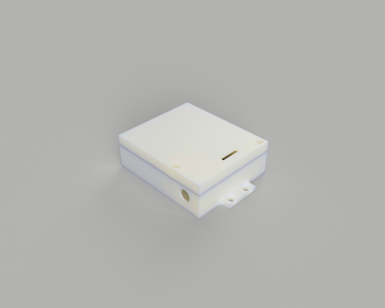
The enclosure was designed around the dimensions of stepper motor driver and the Arduino UNO. I’m using a base that comes with the UNO so that swapping the microcontroller, if needed, will be easy. The stepper motor drive goes directly on the 3D printed piece. It also has a hole for the power inlet and another for the USB cable. Here is a rendering of what it should look like:

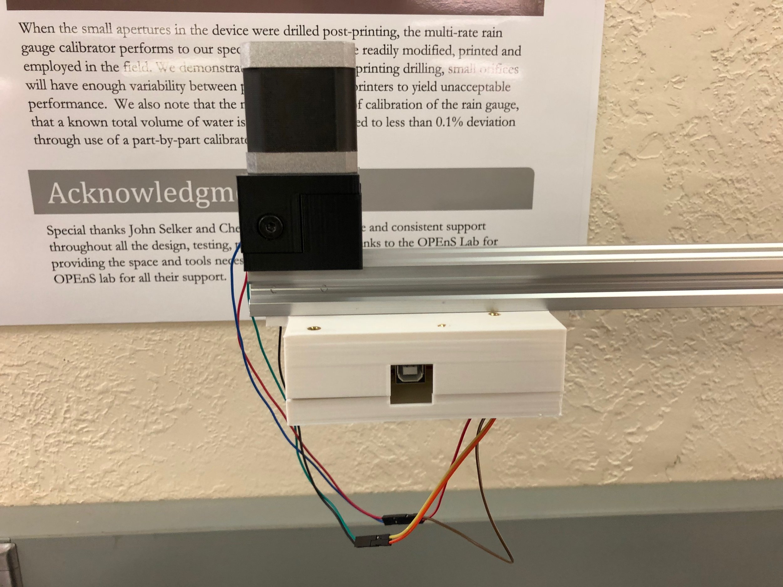
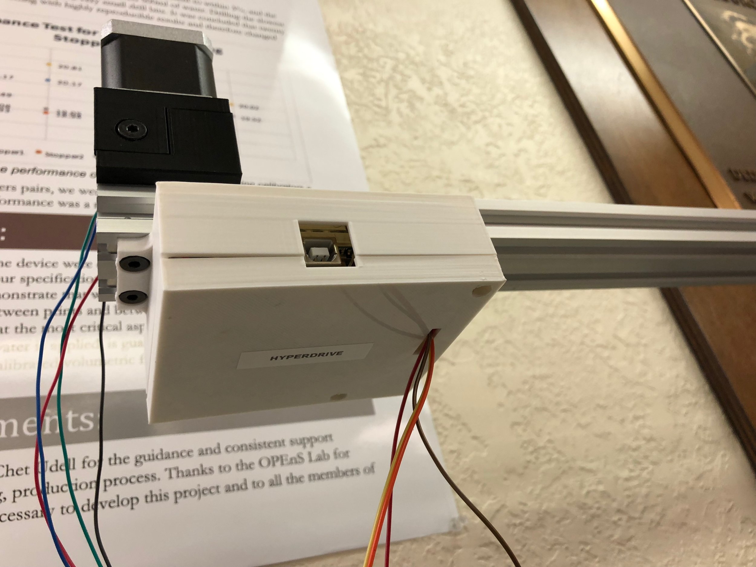
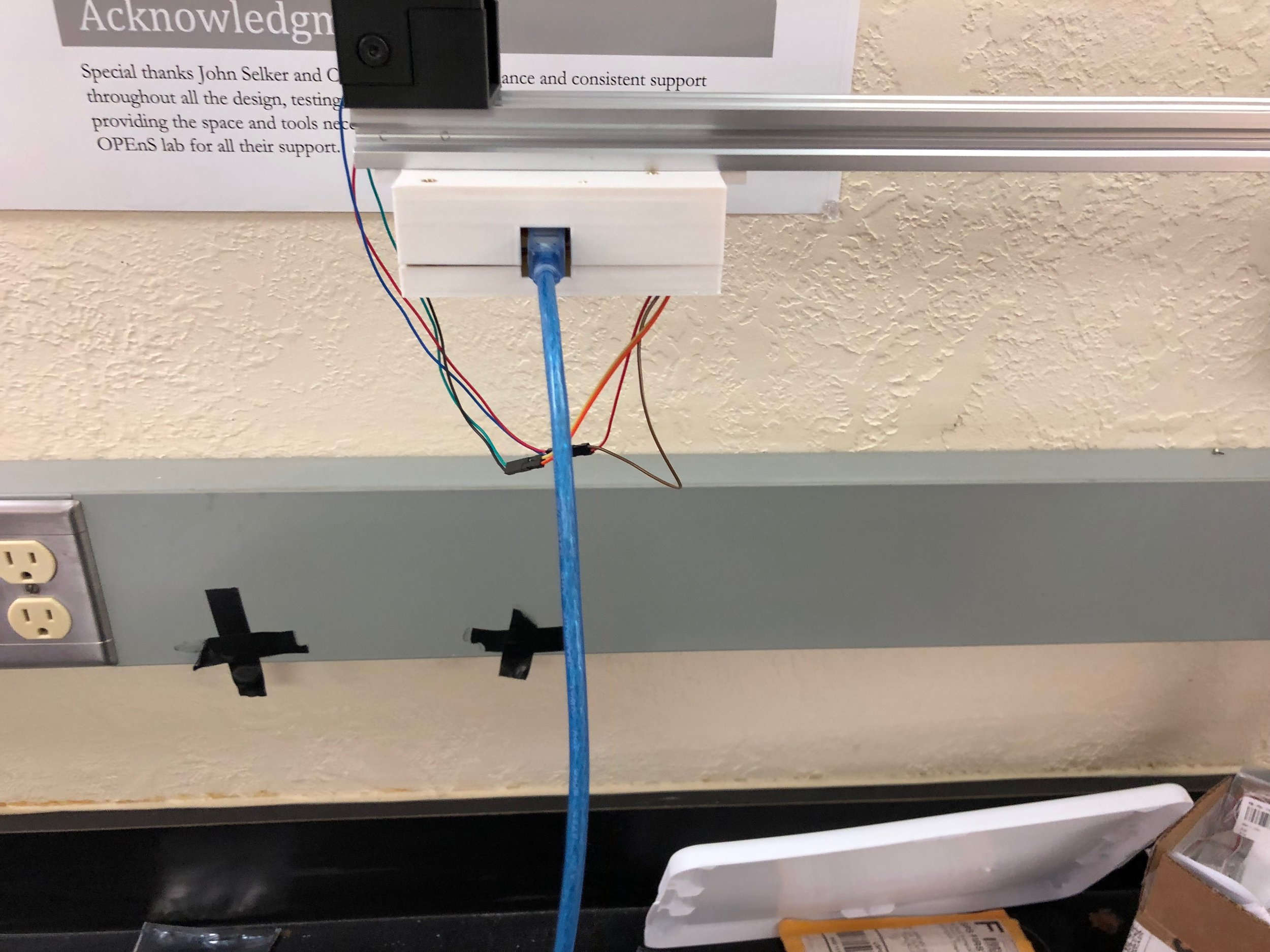
Here is what the actual part looks like when it is assembled:
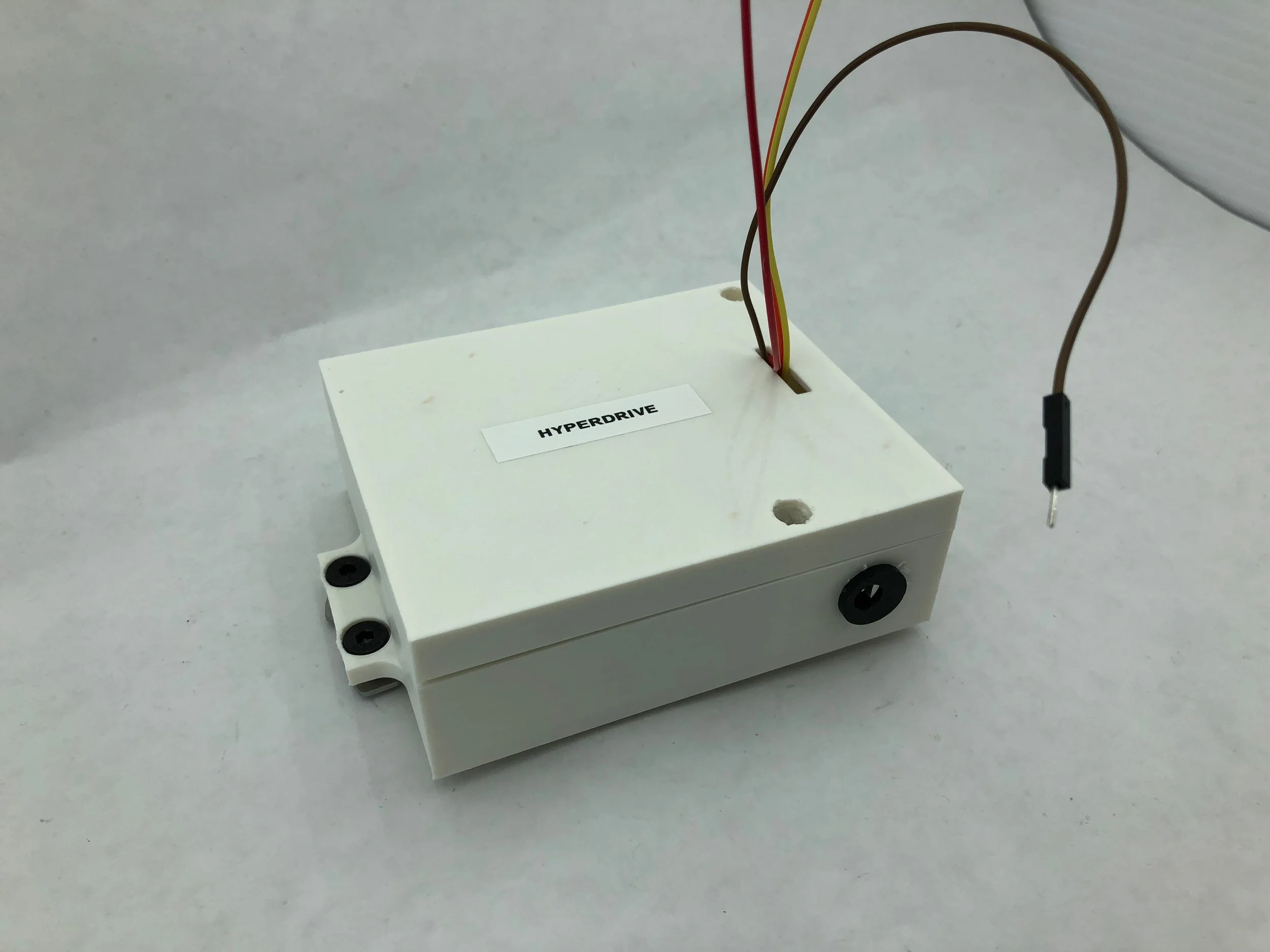

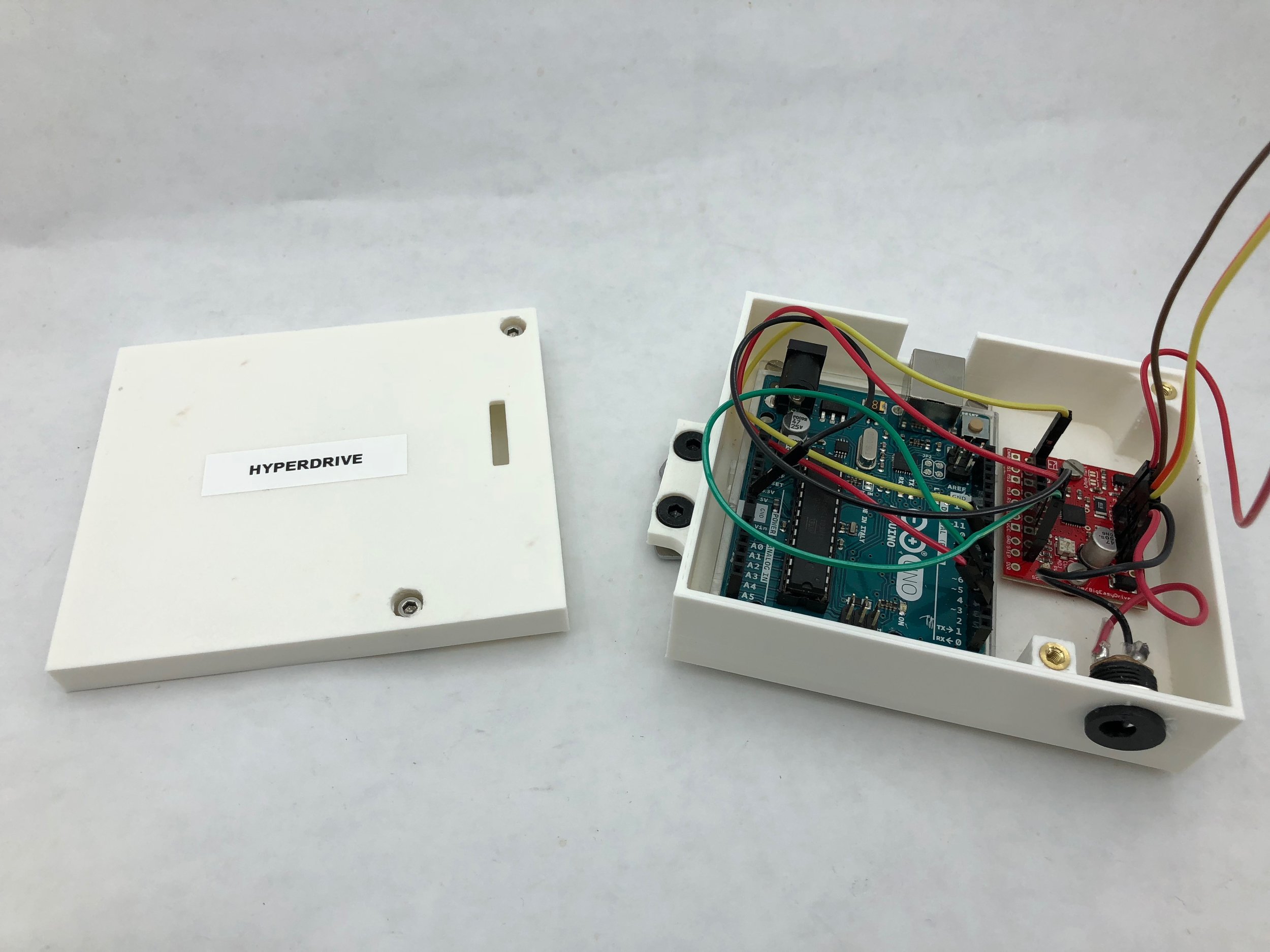

Here are some other images showing it mounted on the aluminum extrusion:
#block-yui_3_17_2_1_1518467028277_76832 .sqs-gallery-block-grid .sqs-gallery-design-grid { margin-right: -20px; }
#block-yui_3_17_2_1_1518467028277_76832 .sqs-gallery-block-grid .sqs-gallery-design-grid-slide .margin-wrapper { margin-right: 20px; margin-bottom: 20px; }
Conclusion:
I am calling this whole enclosure the HyperDrive. This is because it has all the components that are driving the stepper motor. This enclosure makes it easier to move all the electronics around compared to when we had the electronics flying all over the place. Moving on to the next design, I need to make an attachment for the HyperRail to go directly on the greenhouse structure. After that is designed, then the whole system will be ready for install.

