Abstract: The HyperRail was modified to be used with the eGreenhouse, a sensor suite for real-time greenhouse monitoring. The system is about 25.5 meters long and is located in the Northwest Research Extension Center in Wilsonville, OR.
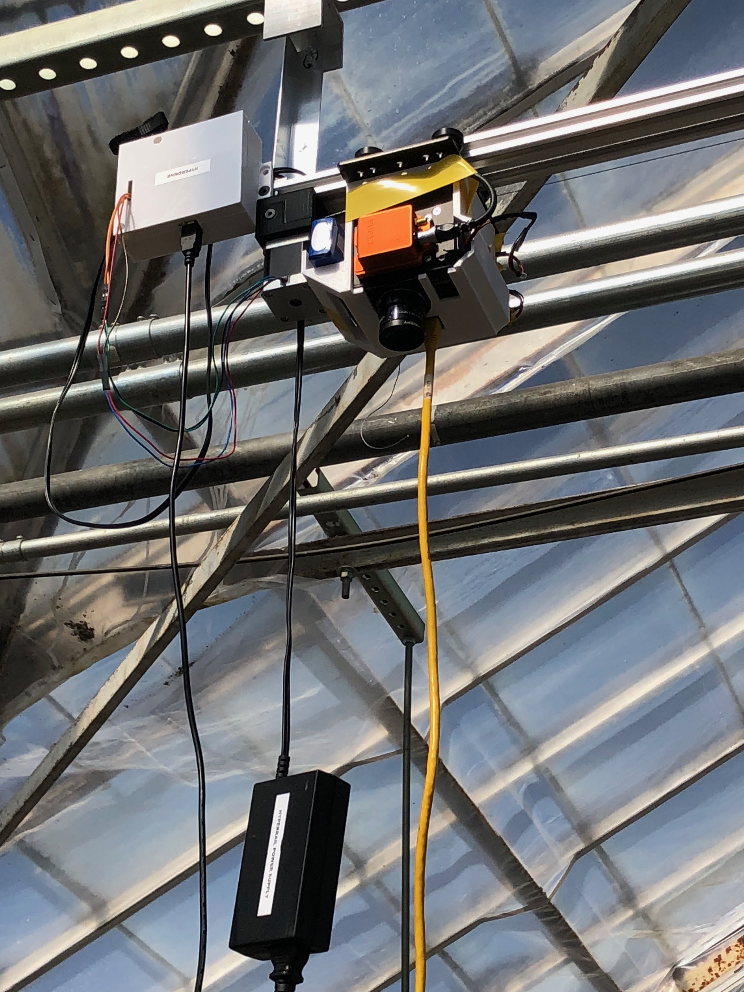
Deployment: The HyperRail has the standard setup of electronics, but in this iteration it includes a short range radio. This radio is used to upload the data from the sensors up to a google spreadsheet. Here is a link to eGreenhouse page that details the the setup of the sensors.
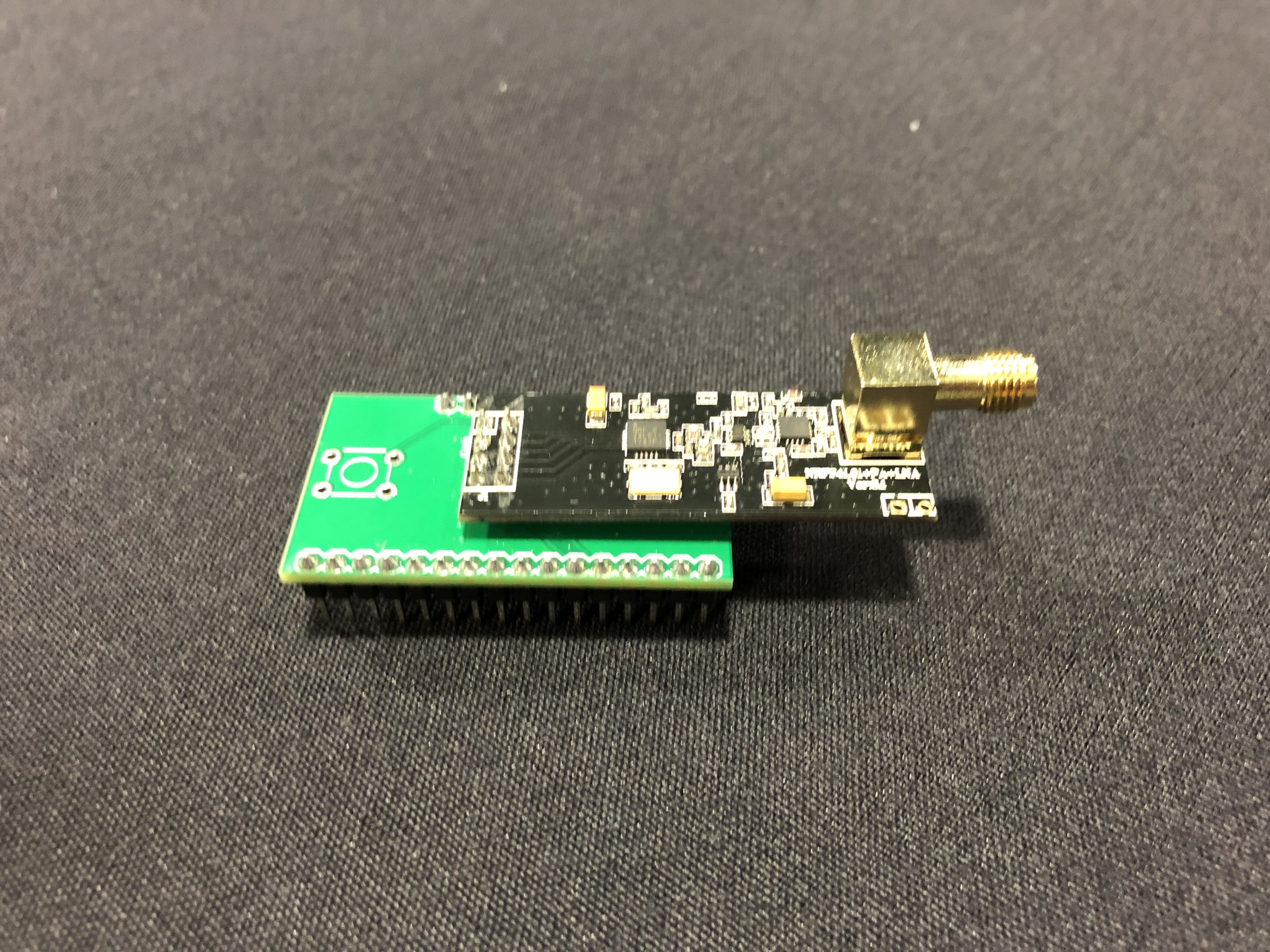
nRF Breakout board
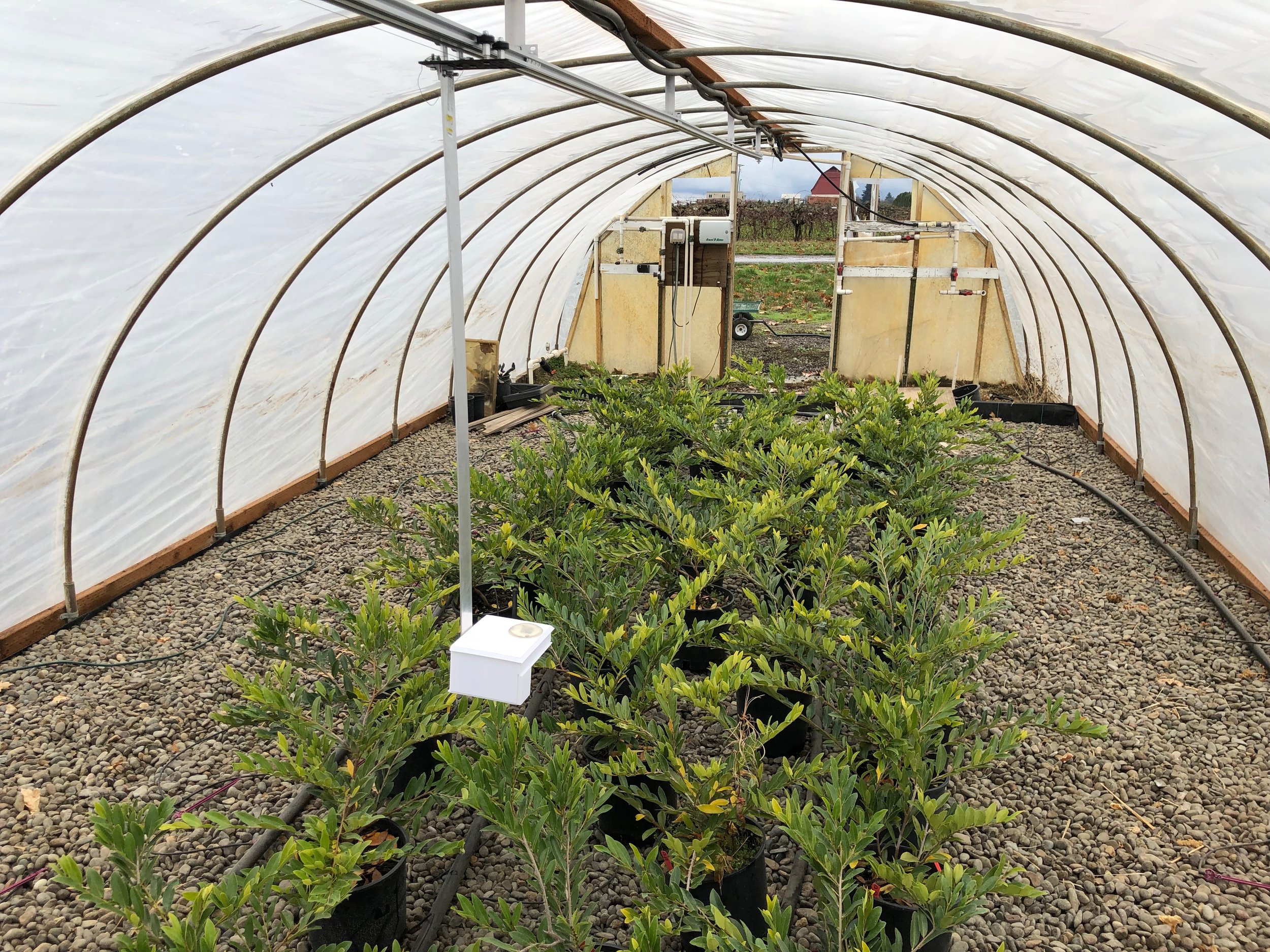
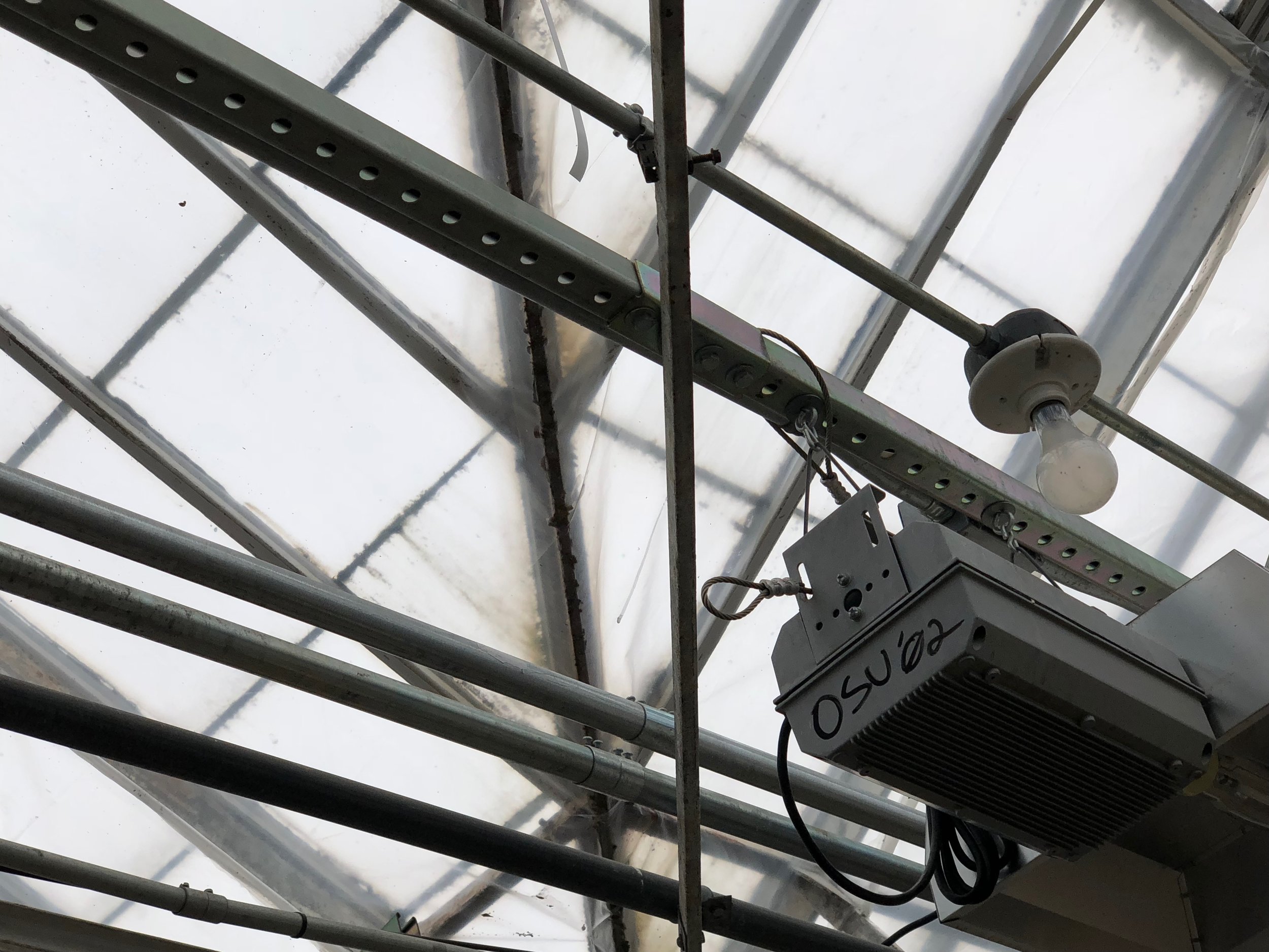
The image above shows the RF chip breakout board that goes on the Feather M0. The image below shows the HyperRail + eGreenhouse deployed in the greenhouse.
Abstract: I have assembled the new evaporometer. This post will be a quick update of the progress.
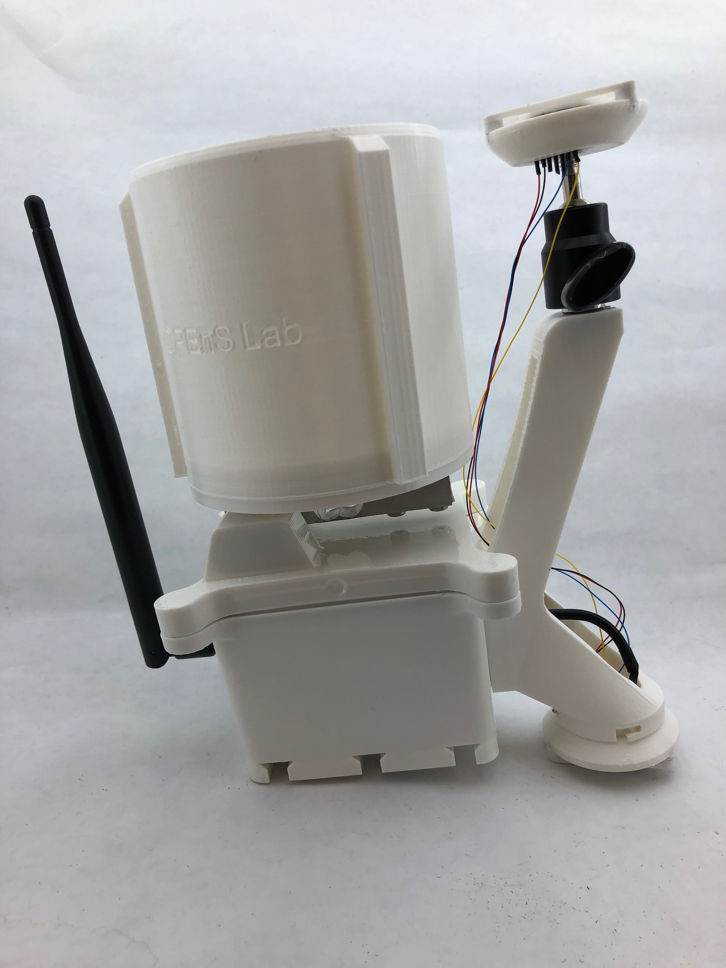
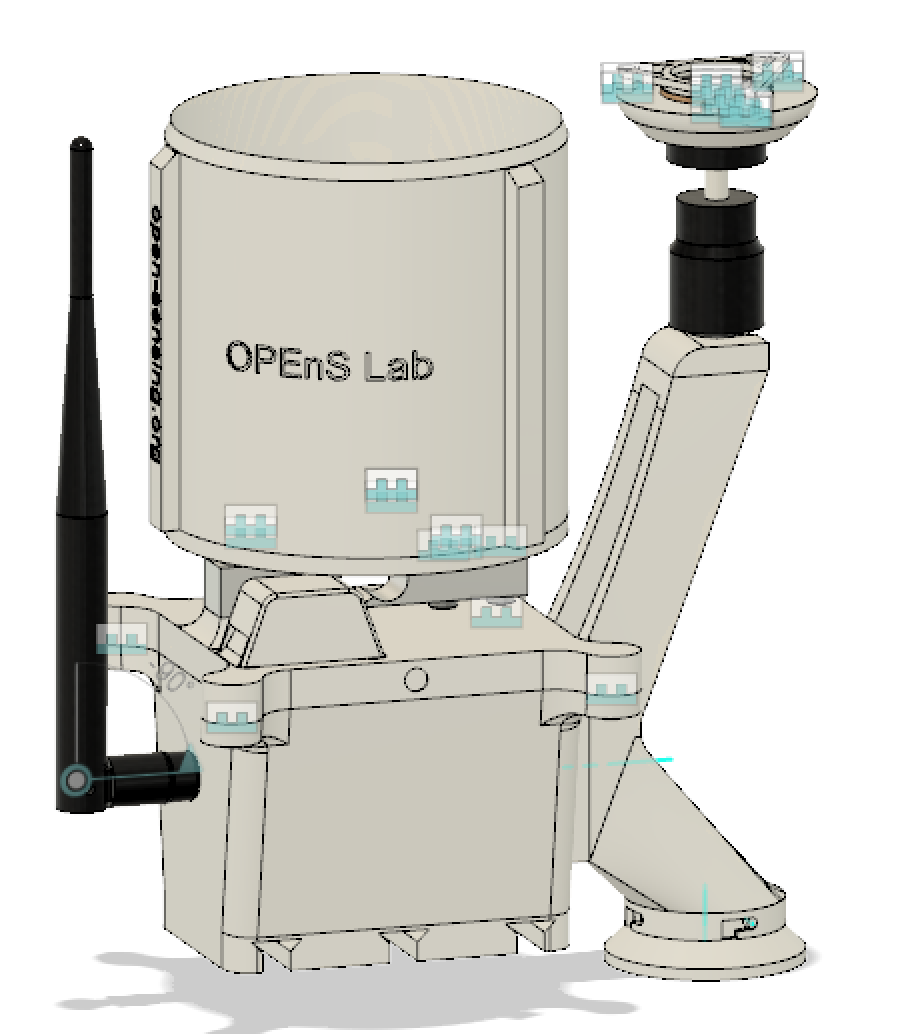
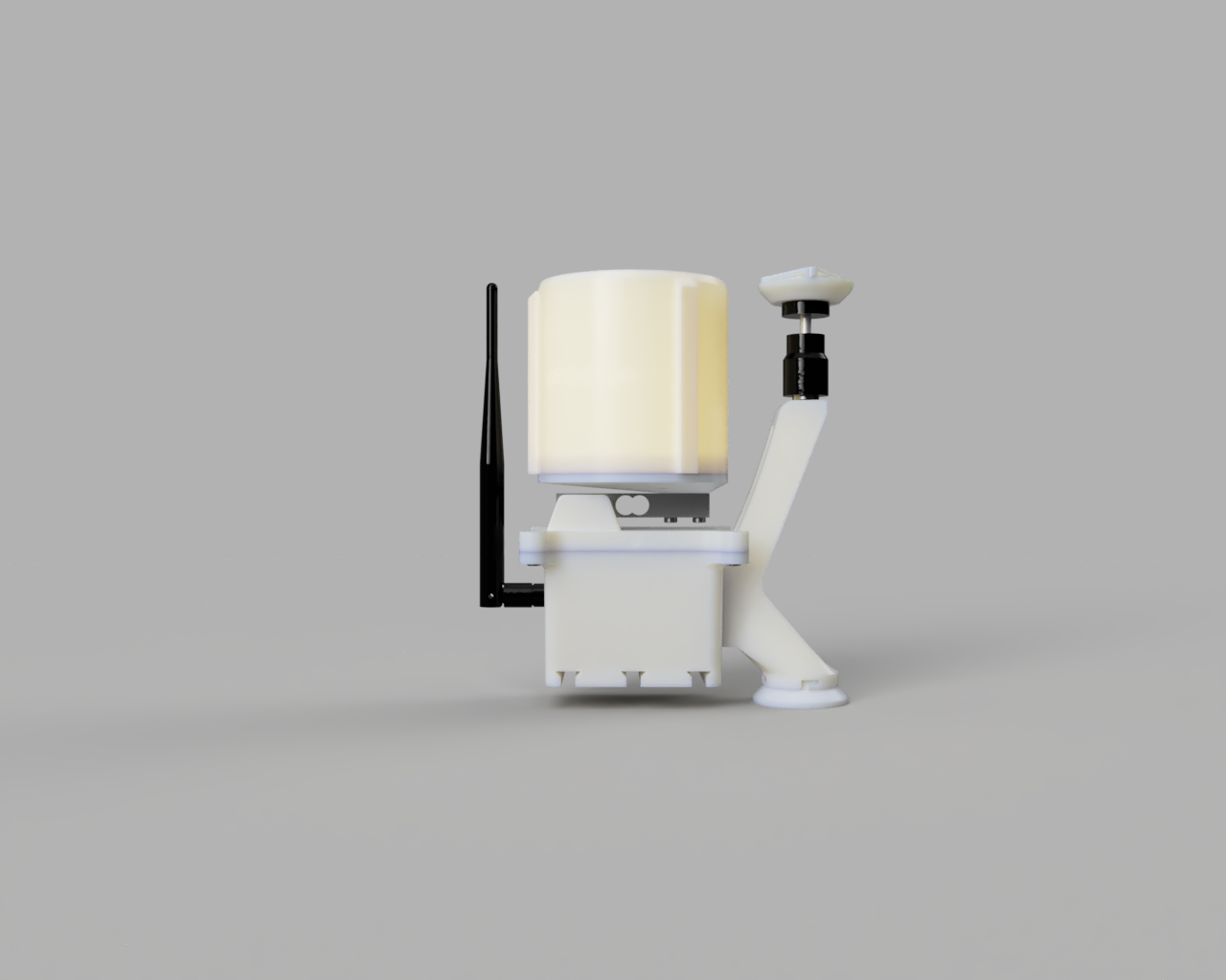
Update: Here is an image of the assembled Evaporometer Type S:
I started by assembling the electronics on the inside because that would be the fastest thing to do. This also included the strain gauge and then humidity/temp sensor that goes on the lid of the system. Then I did the wiring of the light sensors because that would take the longest. The light sensor wiring was the longest because of the intricate soldering on the pins of the sensors, plus passing all the wiring through the cordgrip was very time-consuming.
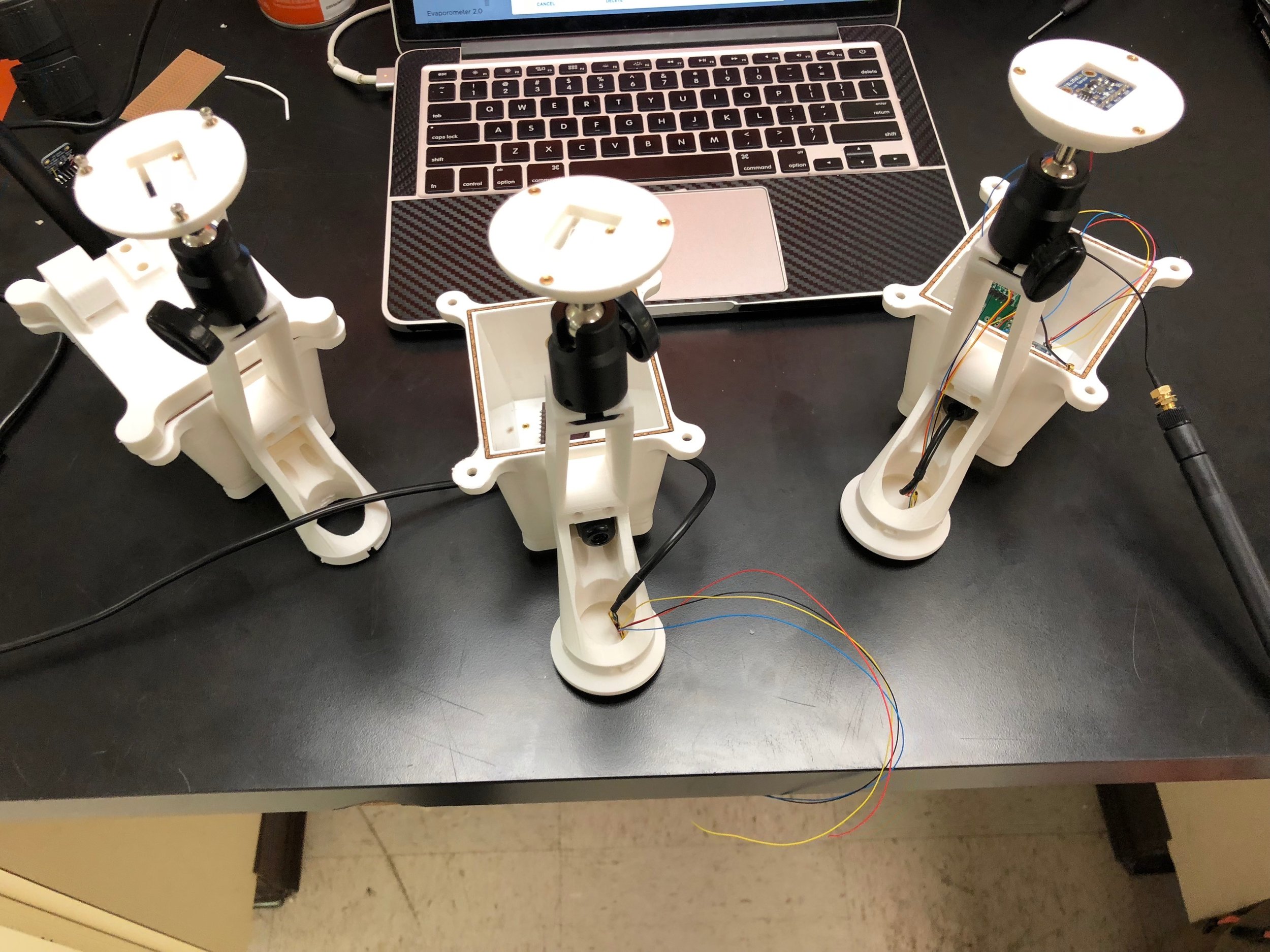
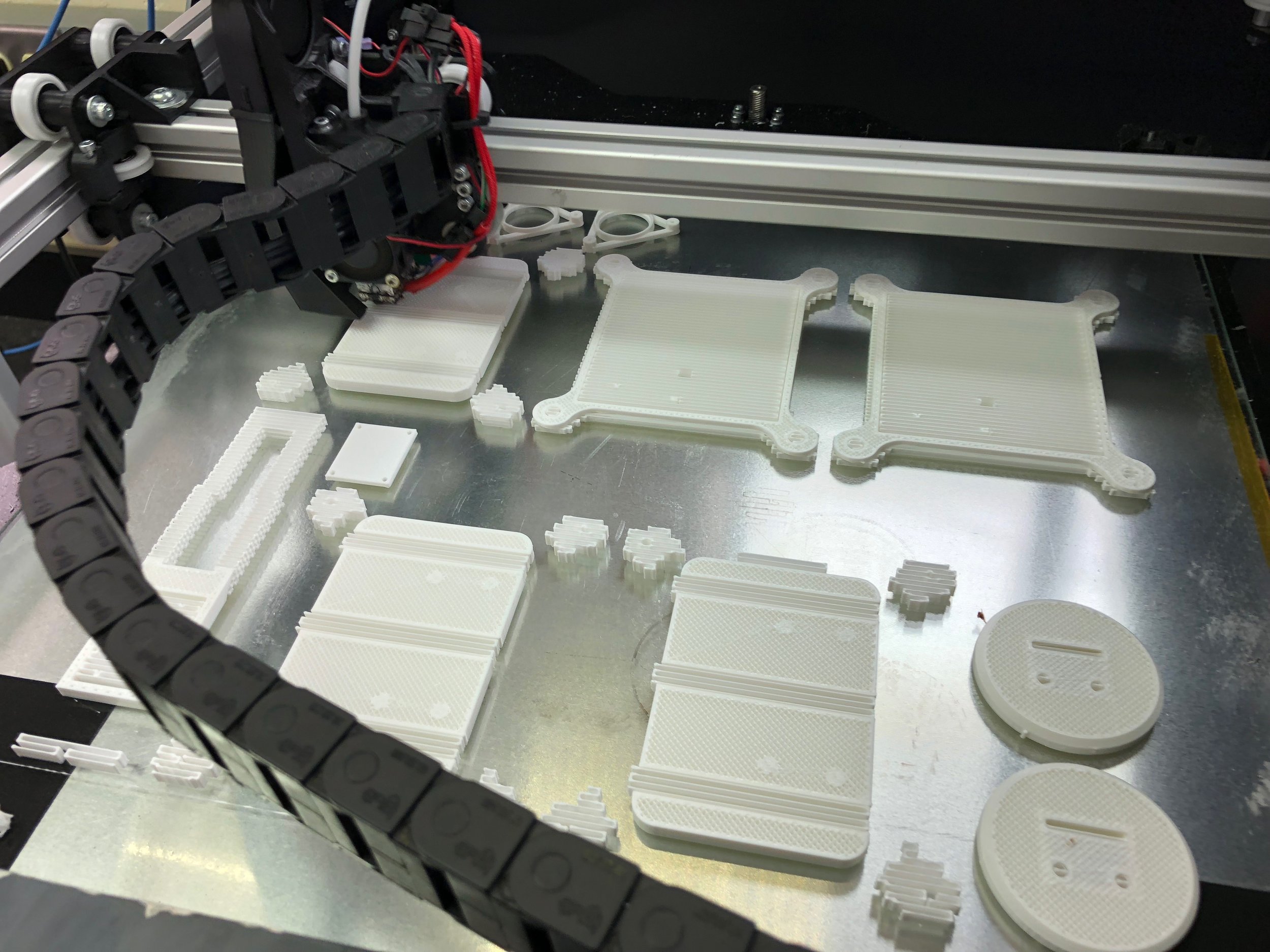
In the end, the whole assembly takes about 2-2.5 hours to accomplish. This is not counting the time to print the parts. At the time of this post, we are still working on three other evaporometers:
And we have more on the printer.
In total we are making four evaporometers with the ETA attachment and four without it.
I have created a new version of the evaporometer where everything is stacked. The main reason for this is to shade the strain gauge from the sun. In this post, I will summarize the design of the evaporometer and show some images of the early iterations of this design.
Design
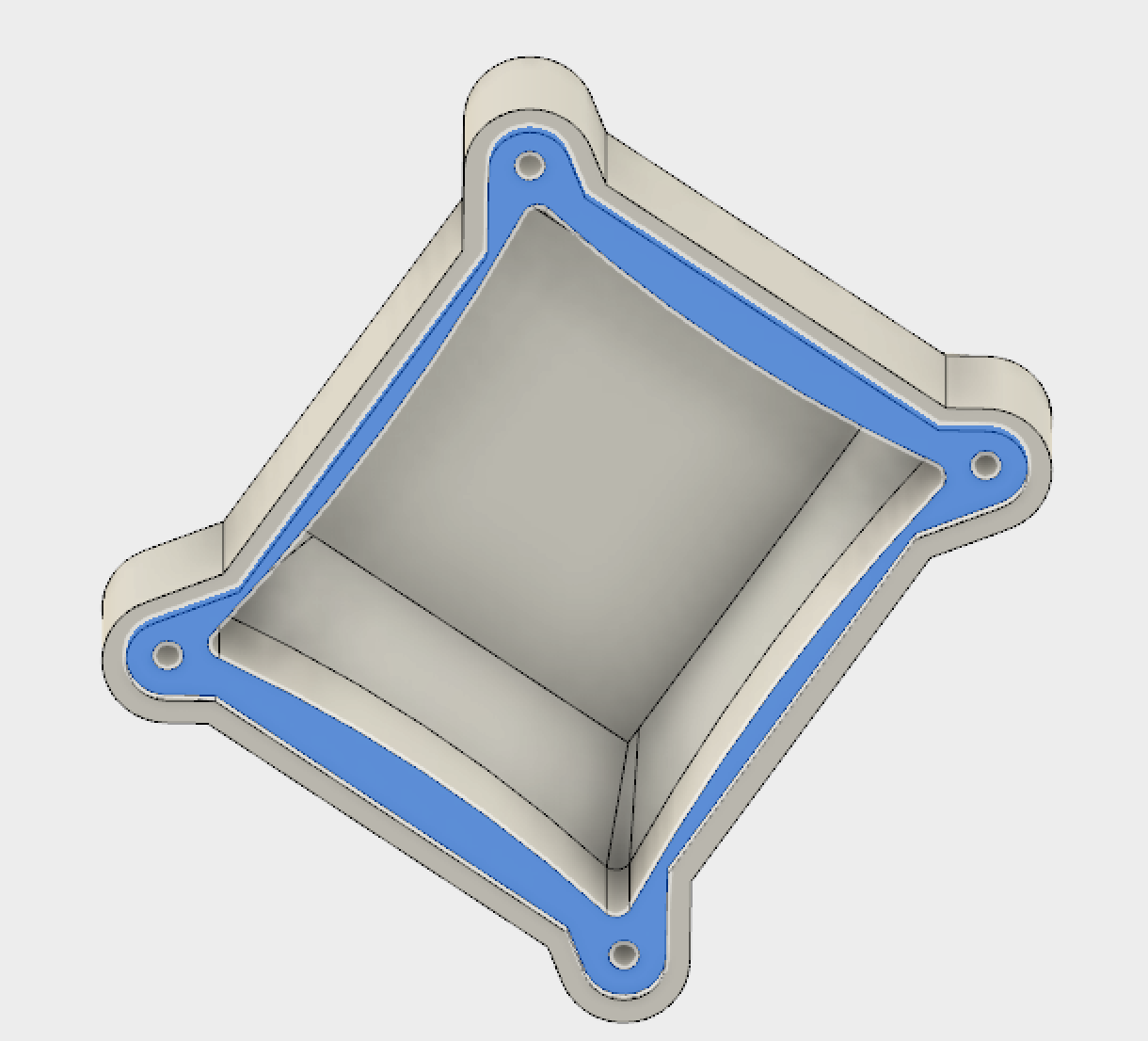
Electronics Case
Electronics case CAD
The image above shows the CAD of the casing of the electronics; inside it will also hold a 6000mAh battery. This part will have an attachment, like the previous versions, where it will have a slide mechanism for easy setup. This version also has a cork gasket so that it will have a better seal between this piece and the cap making it weatherproof.
Electronics Cap
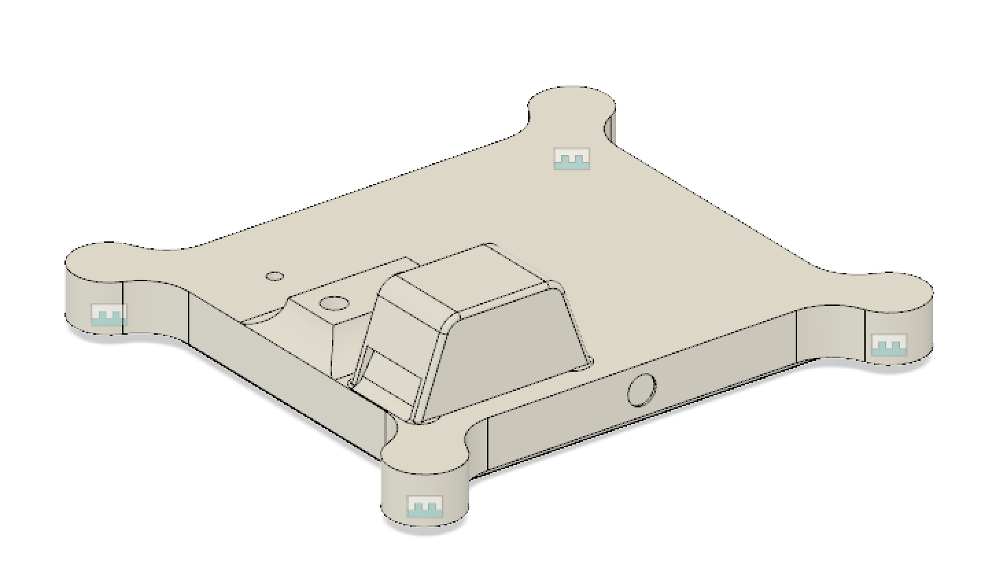
Electronics cap CAD
The image above shows the important elements of the cap. The first, the strain gauge will connect directly to the cap. The second, the little hump that is close to the edge will allow airflow through a slit that will be going right next to the SHT31 sensor, allowing for Humidity/Temp data. And last, the little hole that will allow for the wiring of the strain gauge to go to the microcontroller.
Water Container
The water container was changed much from the last iteration. This iteration alllows for the strain gauge to be connected from the bottom.
Water container CAD
The container is actually made from two pieces. The first piece is bolted to the bottom of the container and then that same piece gets bolted on the strain gauge. The image above shows the assembly of the pieces.
ETA Attachement
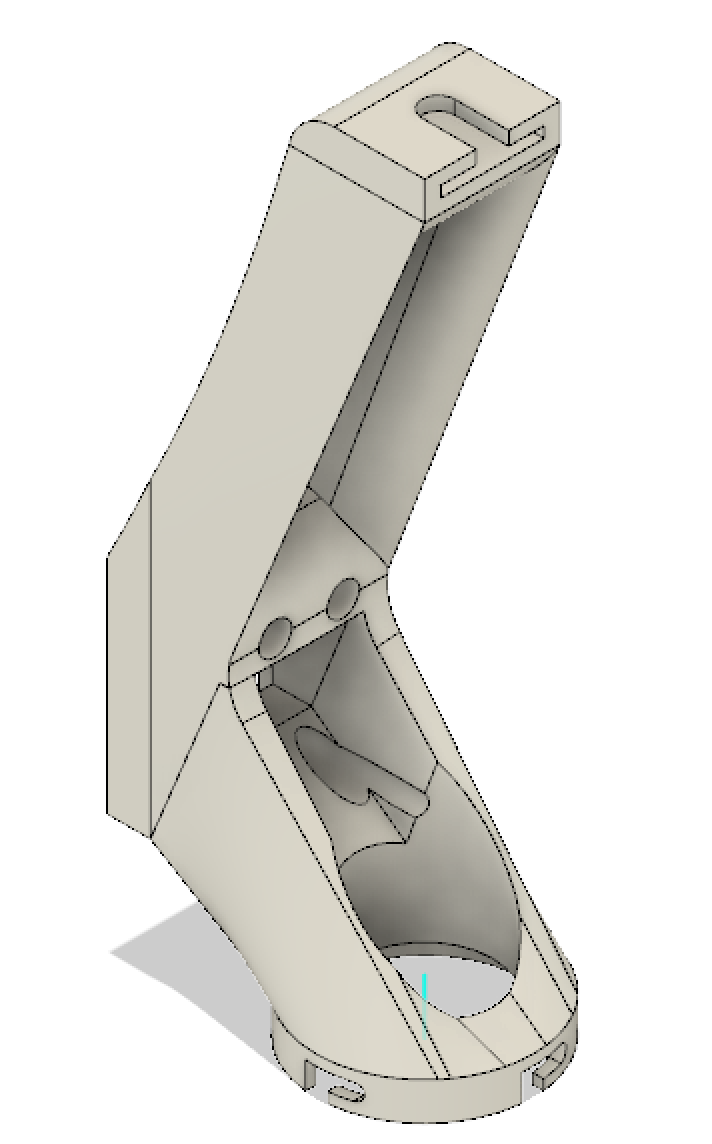
ETA attachement CAD
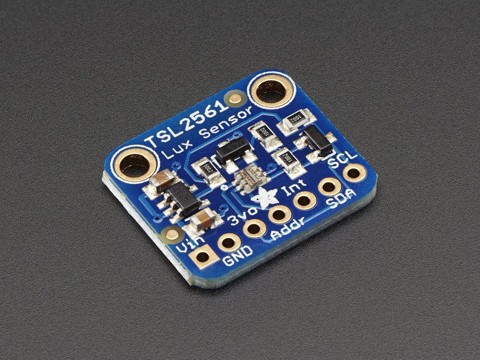
The image above is the attachment that will hold the two TSL2561 sensors. The bottom sensor will have attached using a twist lock mechanism and the top will be on a swivel.
Abstract: The TSL2561 and TSL2591 are Ambient Light Sensors (ALS). Both of these sensors are good, but there are some differences between them that would change the implementation of the Albedo sensor. This post intends to explain why we chose the sensor that we did.
Sensors: Here are links to the two datasheets of the sensors: TSL2561 TSL2591
If the links do not work, you can find the sensors on the Adafruit website by searching TSL2561 and TSL2591.
They both have a broadband photodiode, that includes both visible and infrared, and one dedicated infrared photodiode. It is quite obvious that the TSL2591 has a higher count from the ADC per channel and in turn will be more sensitive to light change. For our purposes, we need a sensor that is going up and one that is going down. Having the higher sensitivity of the TSL2591 would be great, but the limitation to this sensor is that the sensor can only be configured to a single address meaning we can only use one. On the other hand, the TSL2561 has more than one address that can be used; this also means that we can include two sensors for the albedo configuration without the need of extra circuitry such as an I2C multiplexer. For this reason, we will be using the TSL2561. To be able to perform the albedo calculation, it is just necessary to have 2 sensors outputting the same kind of data out. This means that we can go ahead and use the TSL2561 and it should be just fine.
TSL2561
Conclusion: The TSL2561 is sufficient for our albedo sensor. The major upside is that we can use two sensors; this is because of the multiple addresses that the sensor can be assigned. The only downside is that it is not as sensitive to light as the TSL2591, but this should be not a problem as we only need two reliable sensors outputting the same kind of data to be able to perform the albedo calculation.
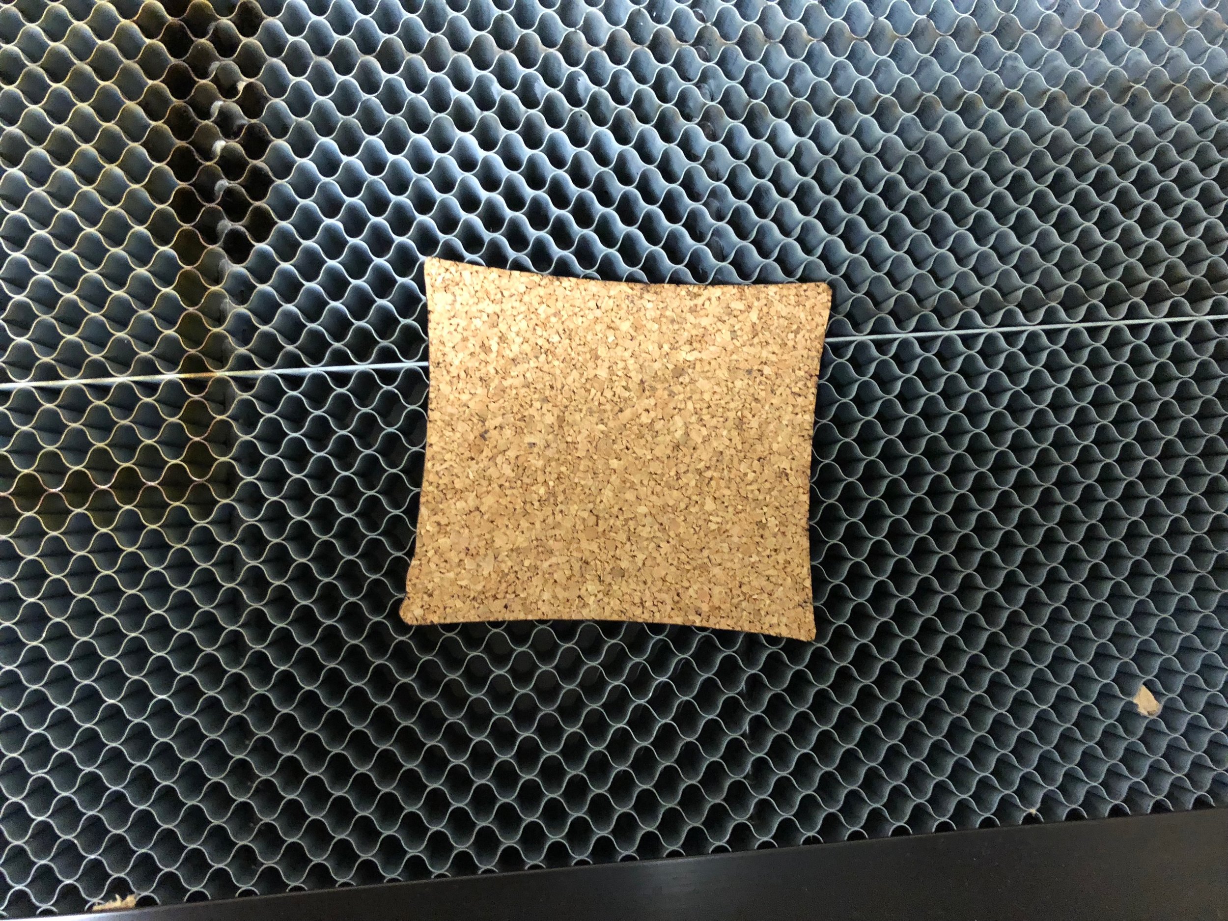
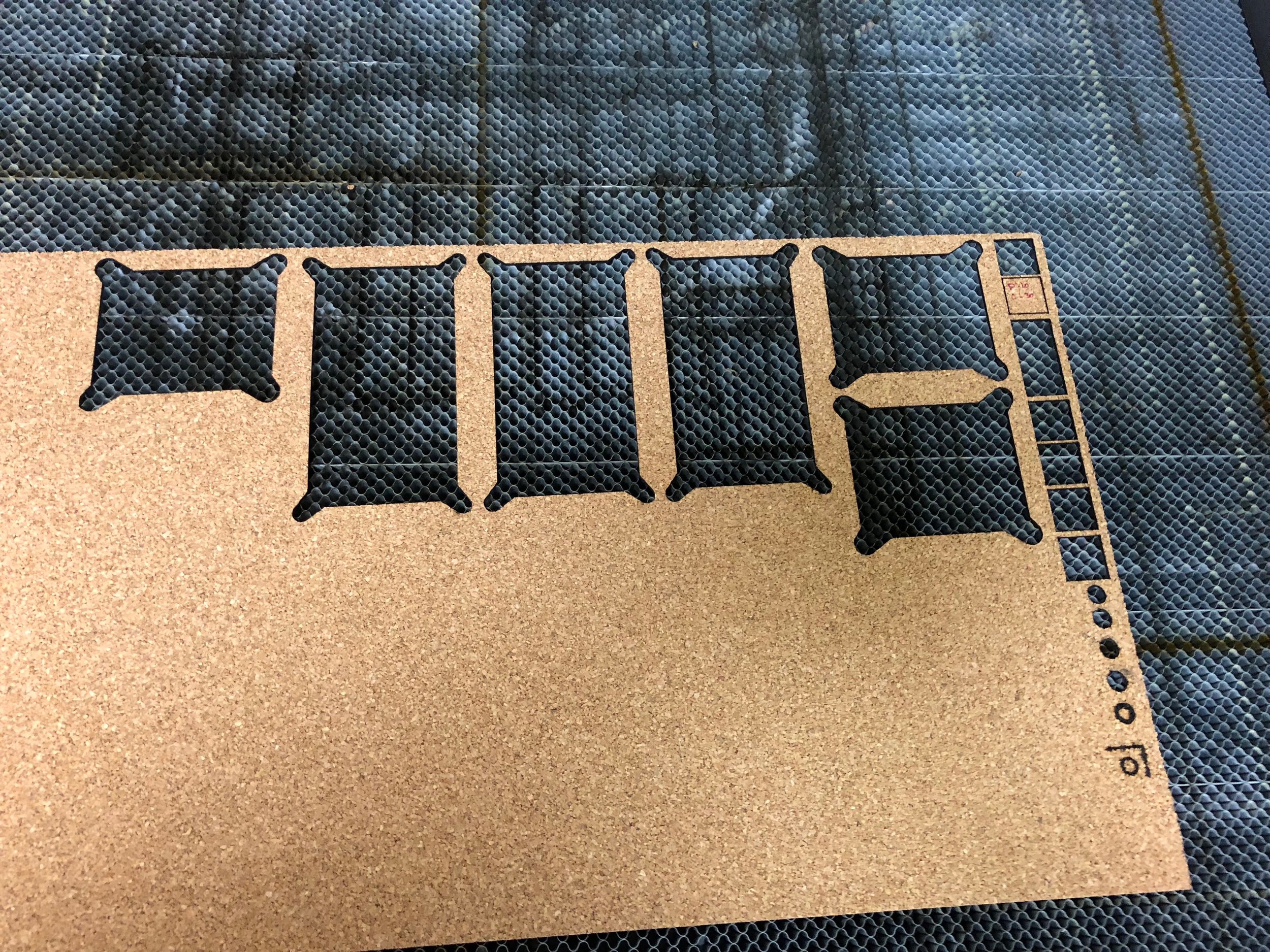
Abstract: We have been looking for a way to seal our enclosures so that water can’t get in. In response to this problem, we decided to use cork to try to solve this problem. This post is just a brief description of what the design looks like and the settings used to cut the cork.
Design:
I used the face of the bottom part of the cap to create the gasket design. This was done very easily using the project command and then extruding face out 1/16 inches.
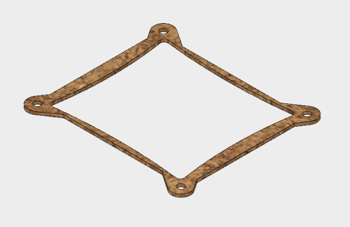
Face of where the gasket goes and where the projection was taken from
Gasket rendering
The design didn’t take much time, but figuring out the laser cutter settings did take time. I was able to determine that the optimal settings to cut the cork were at a speed of 30 mm/s and a power of 15% on our laser cutter. Here are some pictures of the cuts:
I got this material from McMaster-Carr. This other link also gives some characteristics of cork.
Conclusion:
This is being put to the test, as we just deployed four sensor suites and they were all equipped with this gasket. We will see if it is able to keep the electronics safe from moisture and running until the battery dies or the term comes to an end.
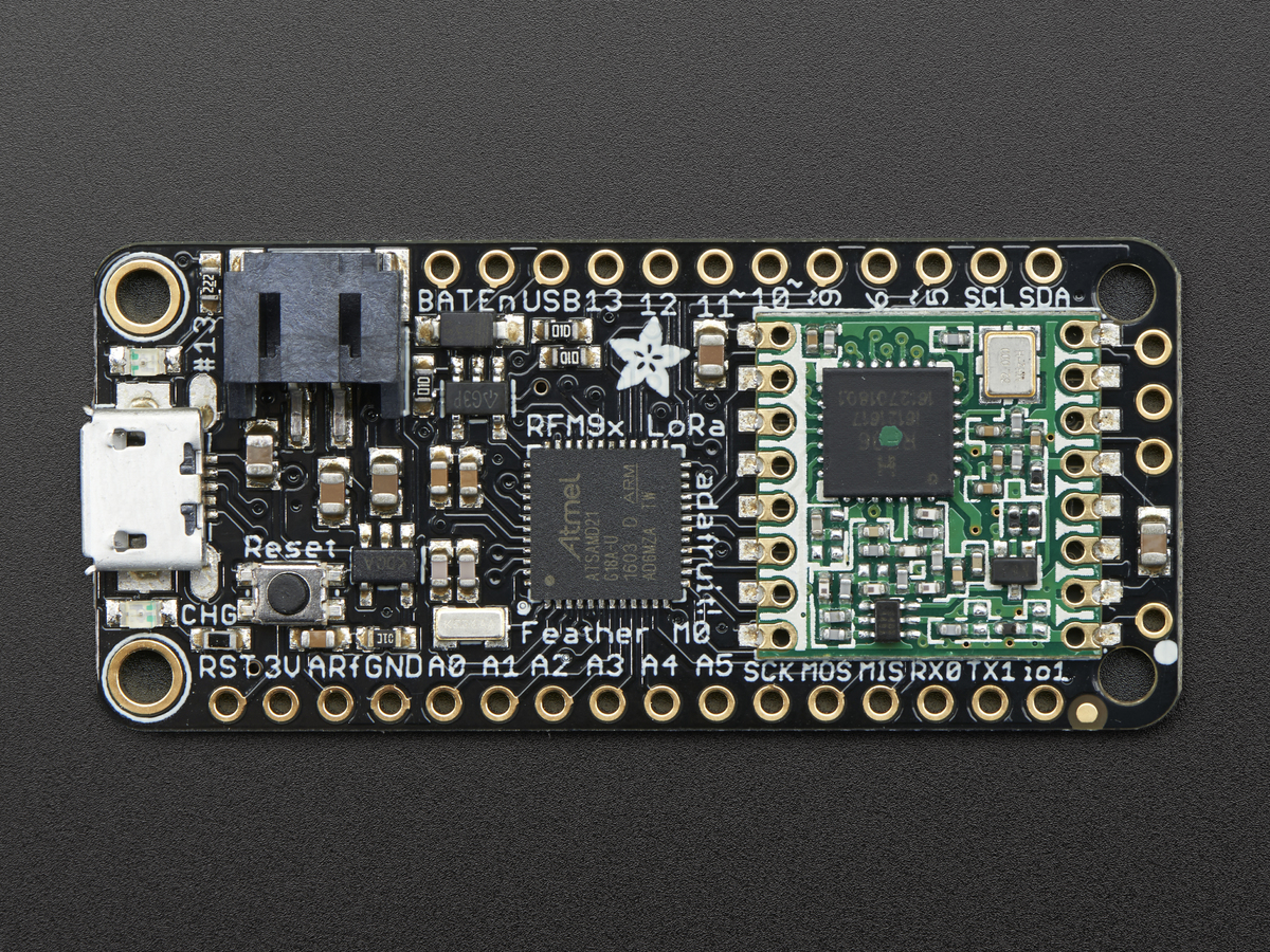
Abstract: We are trying to improve the capabilities of the HyperRail to have wireless communication with other sensors, and in order to do that we needed to upgrade the microcontroller. I’ve tested the Feather M0 LoRa with the HyperRail and it works. This post is a summary of the integration of the new microcontroller.
Design: The code was made modular so that it could be used on any microcontroller that could handle delays in the microsecond range and serial communication. The program also doesn’t make use of any libraries for the HyperRail to work. The Feather M0 LoRa is a great option for the HyperRail’s wireless communication upgrade because not only does it do serial communication and can handle microsecond delays but it can also do radio communication. Here is an image of the new microcontroller:
Feather M0 LoRa
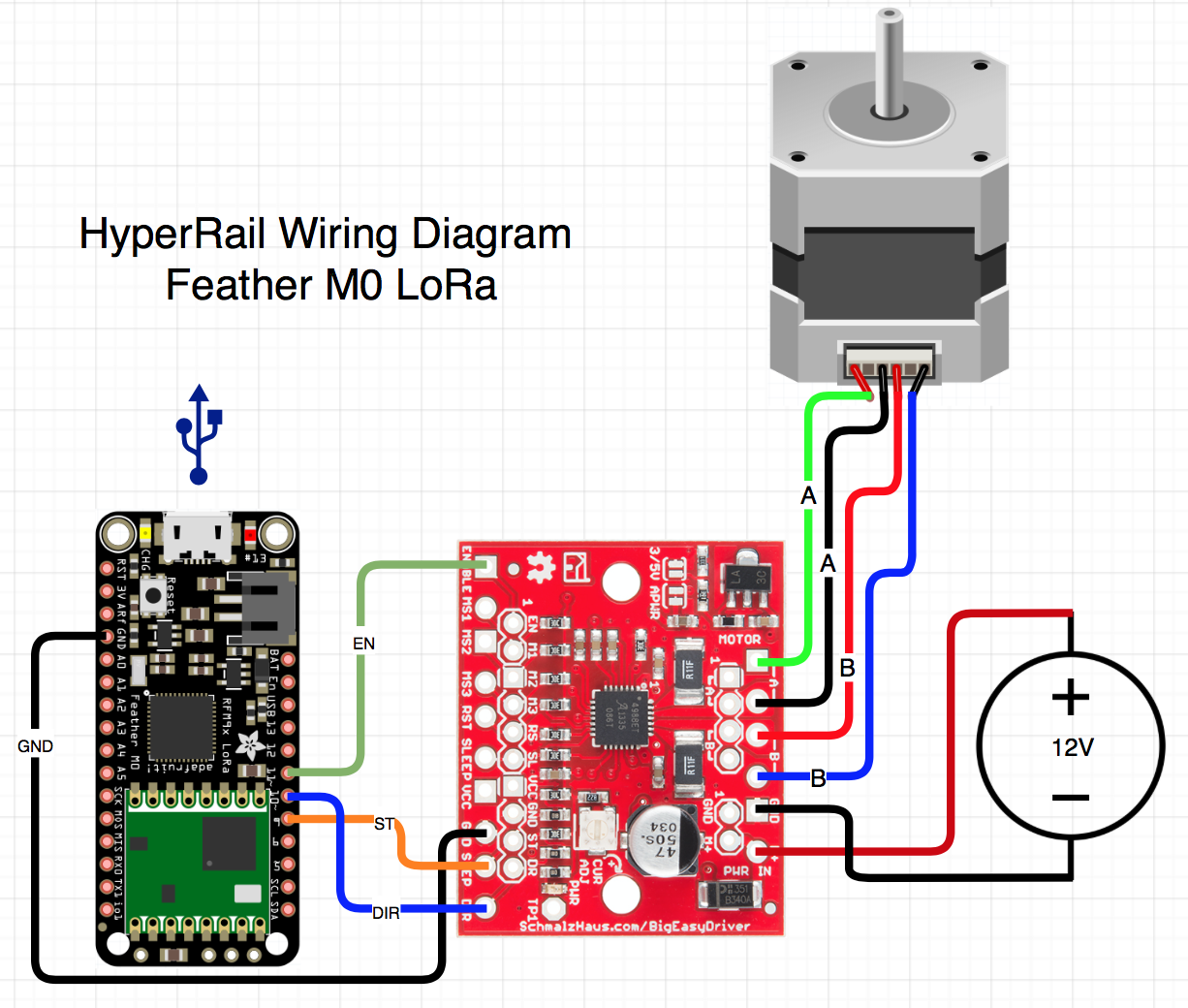
Here is the wiring diagram of this configuration:
Wiring diagram
With some minor changes in the code, I was able to get the system working with the new microcontroller. Although the changes were minimal, it took some time to figure out what to change. One thing that wasn’t working was the serial communication, this is essential for the system to work. What was happening is that the Feather was outputting the serial prints way faster than the serial port would open, so I had to put in some checks for the serial port communication to be established first before any print statements were executed. Another thing I had to change was the pins used for the communication to the stepper motor driver.
Conclusion:
The upgrade to the new microcontroller went very well. I will now try to start sending commands to the microcontroller from another Feather and see how it responds. Here is a video covering the same points with a demo:
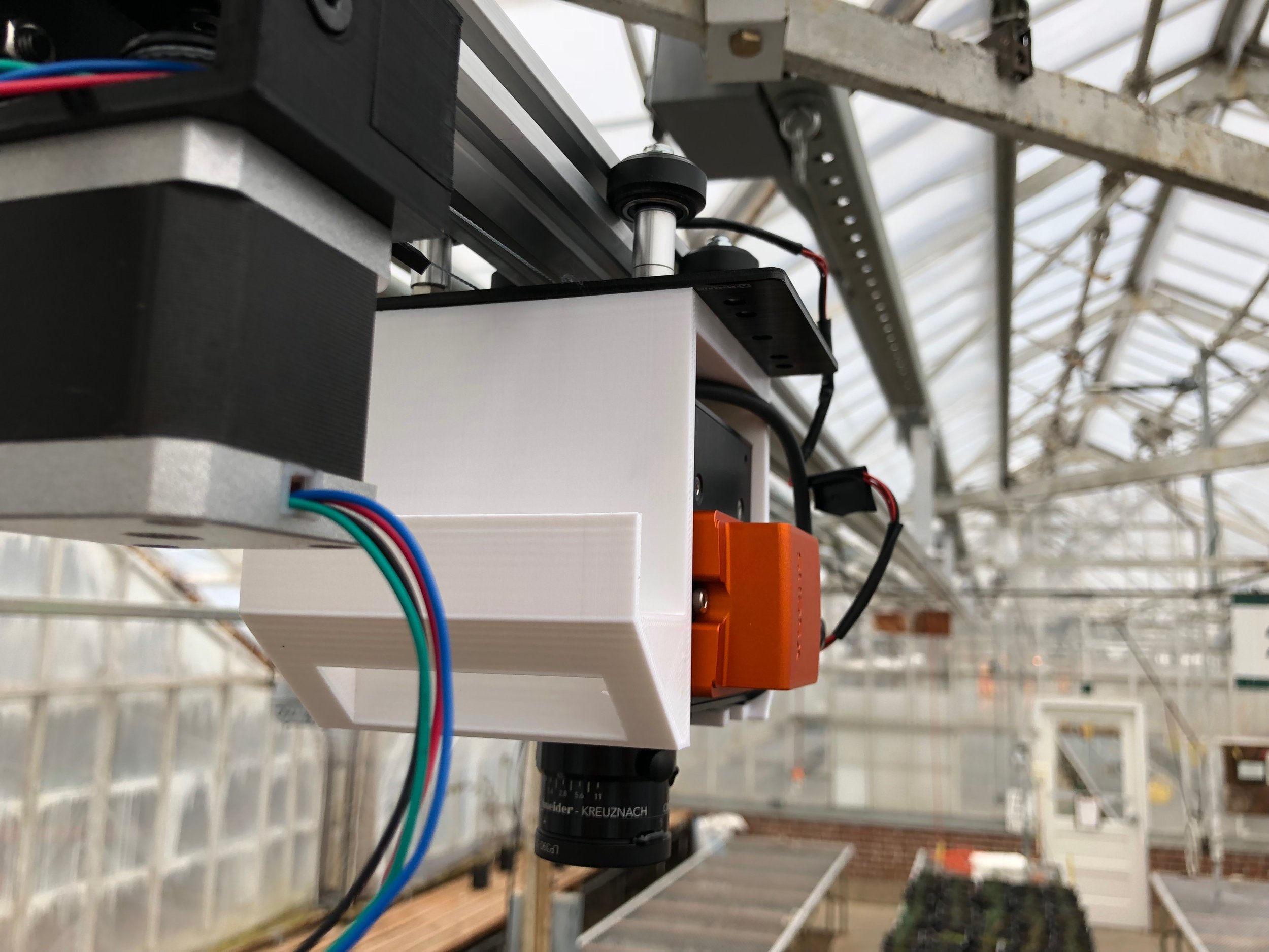
Abstract: We took our first set of data of the pine seedlings using the HyperRail and hyperspectral camera. This post will be a summary of our setup for the data collection.
Objective: Inform about our setup of the HyperRail and give an overview of the data collection.
Setup We are using 9 meters of V-Slot (aluminum extrusion), a gantry set (rolling base), all the 3D printed parts located here, this attachment, an Arduino UNO, and the Big Easy Driver. The code is also located in the code section of the main page of this project.
Data collection Steps
1. Upload the sketch to the Arduino Uno and connect the computer to the microcontroller
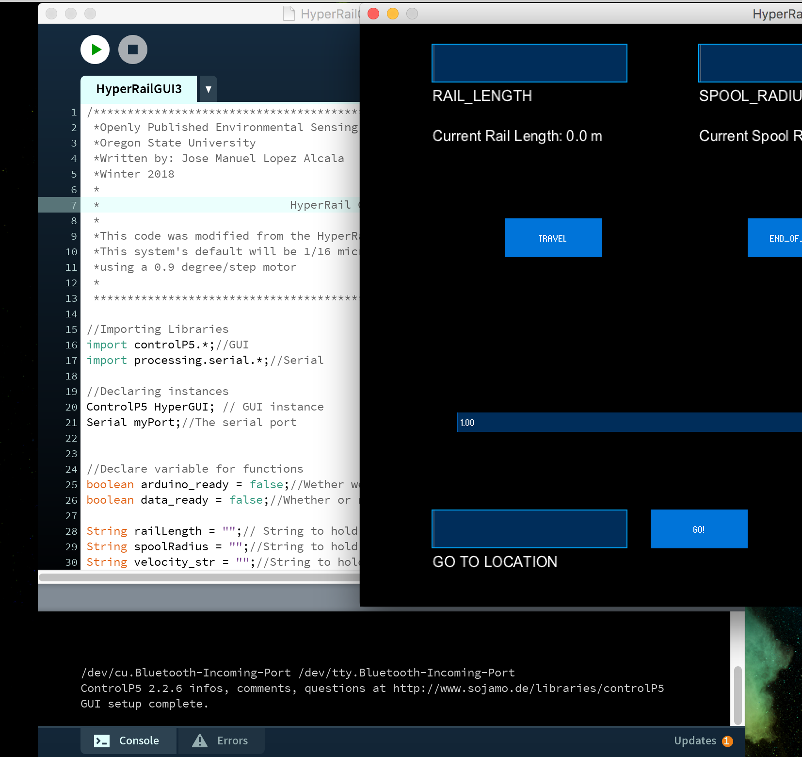
2. Run Processing sketch and wait for the list of ports to appear on the bottom of the IDE of processing. It will say something like, “/dev/tty…” or “com#”
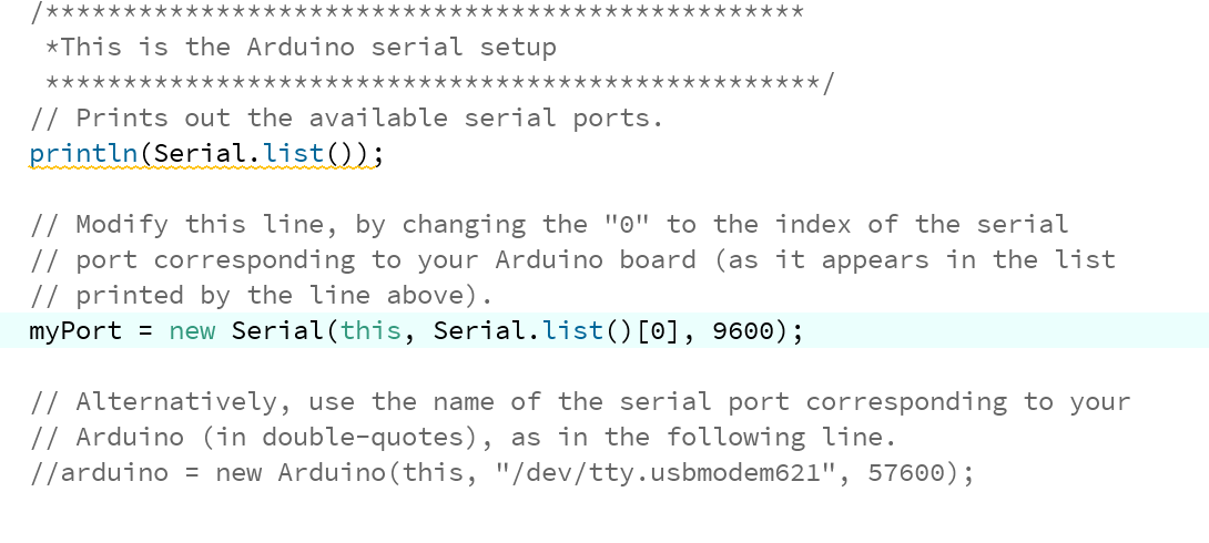
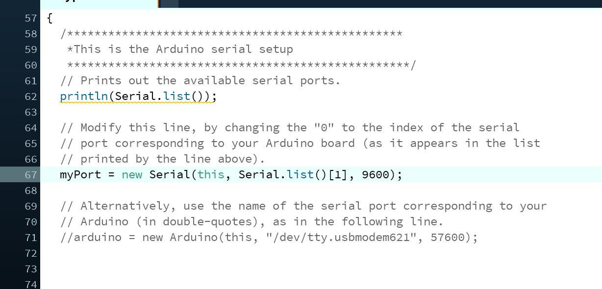
3. Change the port that the microcontroller is connected to in the code. Note that the ports are enumerated starting at the index of 0. An example would be, ” /dev/cu.Bluetooth-Incoming-Port /dev/tty.usbmodem621″ you would select port 1. Here is an example of the change of the port:
Port located at index 0
Port located at the index 1
4.Run the code again and wait for the IDE to say “GUI setup complete” and a single “r”. The “r” is very important because that means that the microcontroller is communicating with the application and is ready to receive a command from the application; the are stands for ready. After this step, the HyperRail is ready to go. Now we need to setup the hyperspectral camera.
5.Insert the camera in the case and then bolt in from behind or put a strap on the front. The bolts or strap are there for extra safety, not really neccesary, but it is still good to have.
6. Hook up the battery and turn on the camera.
7. Attach ethernet cable and start the data collection.
8. Detach the ethernet cable.
9. Star the HyperRail and wait for it to travel the rail.
DEMO VIDEO:
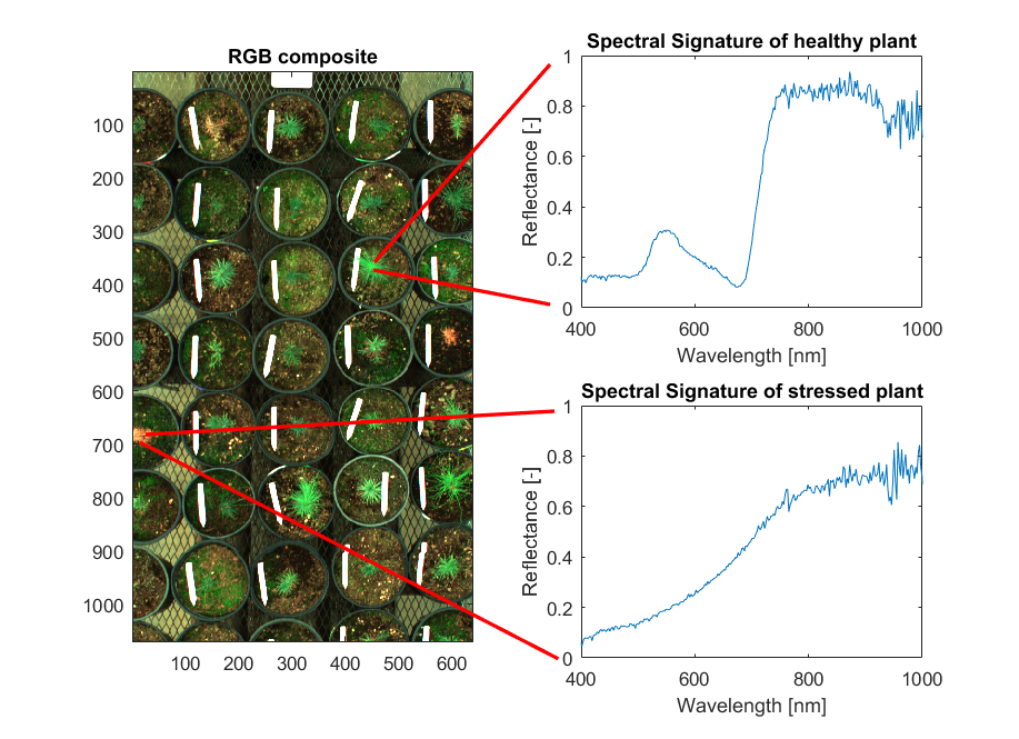
Here is an example fo the data collected from the hyperspectral camera:
Conclusions: The HyperRail is working well. We will now move to improving the GUI for more functionality and upgrade the electronics for autonomous operation. This means that the sensor will in charge of moving the HyperRail’s carriage to where the sensor needs to be. We will be implementing the Feather microcontroller from Adafruit to do this because it has a LoRa radio to be able to communicate easily between feathers. I also need to run validation tests for the performance of the HyperRail to verify the precision of the movement of the carriage.
Abstract: The GUI works and everything is starting to come together. One of the last things is the housing of the electronics. I designed an enclosure that will have the microcontroller and stepper motor driver directly mounted on the aluminum extrusion. Objective: I intend to give an update on the enclosure’s design and implementation of the electronics. I will also give an update on the GUI status. GUI: Here is a demo of what the GUI looks like in action!
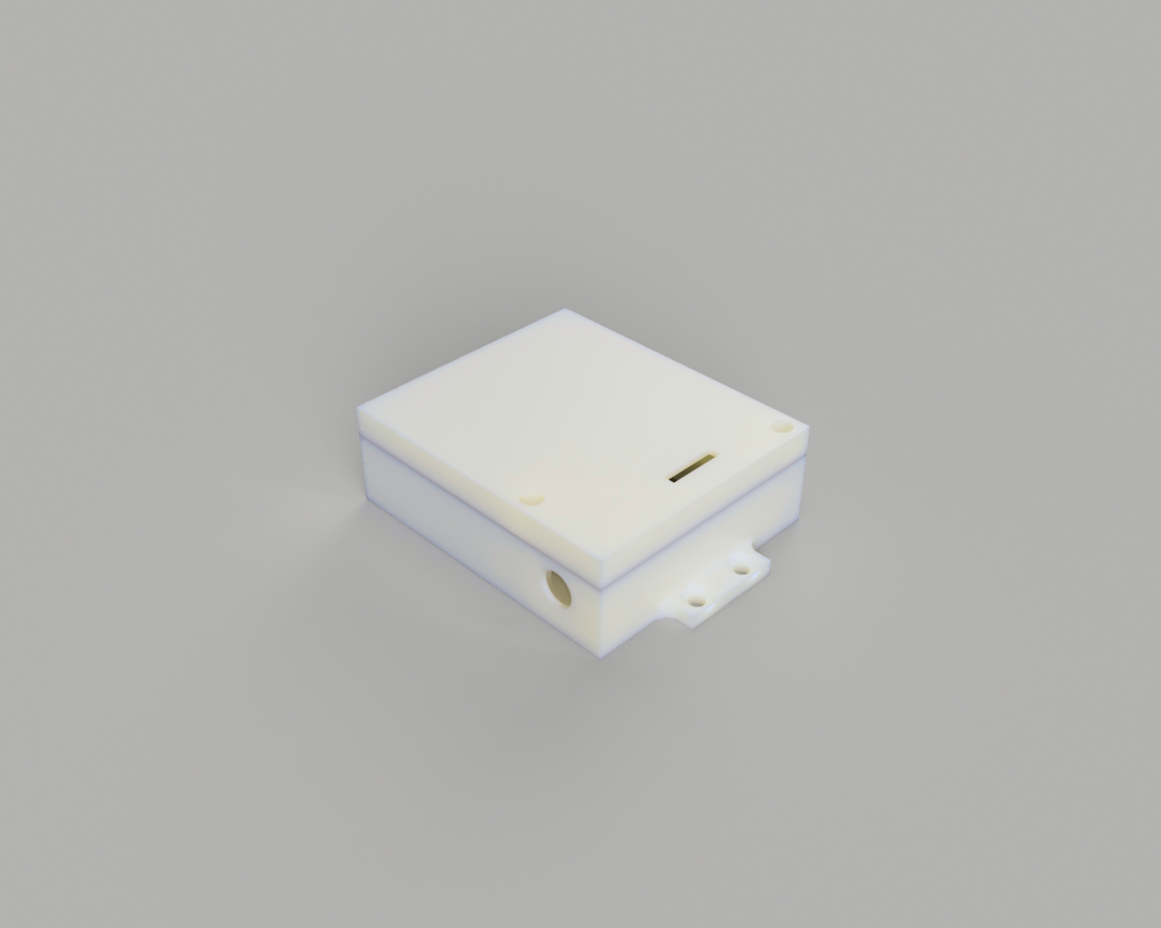
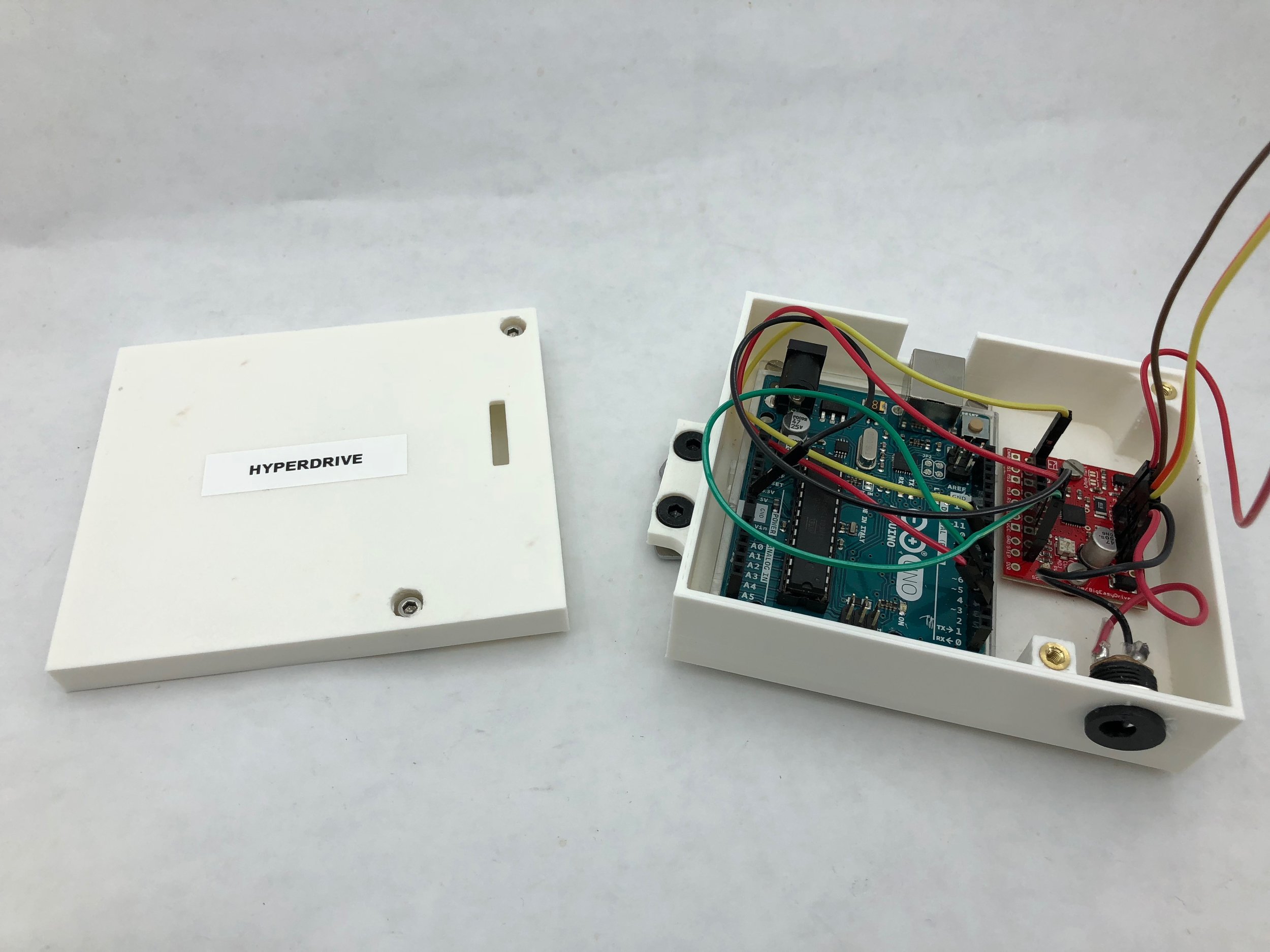
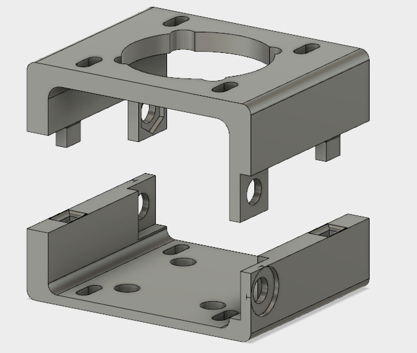
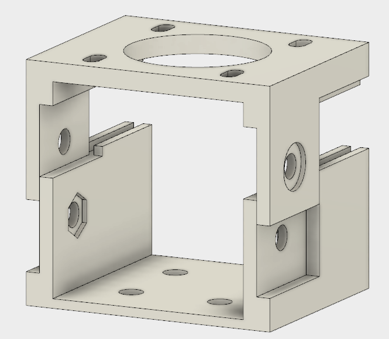
Enclosure: The enclosure was designed around the dimensions of stepper motor driver and the Arduino UNO. I’m using a base that comes with the UNO so that swapping the microcontroller, if needed, will be easy. The stepper motor drive goes directly on the 3D printed piece. It also has a hole for the power inlet and another for the USB cable. Here is a rendering of what it should look like:
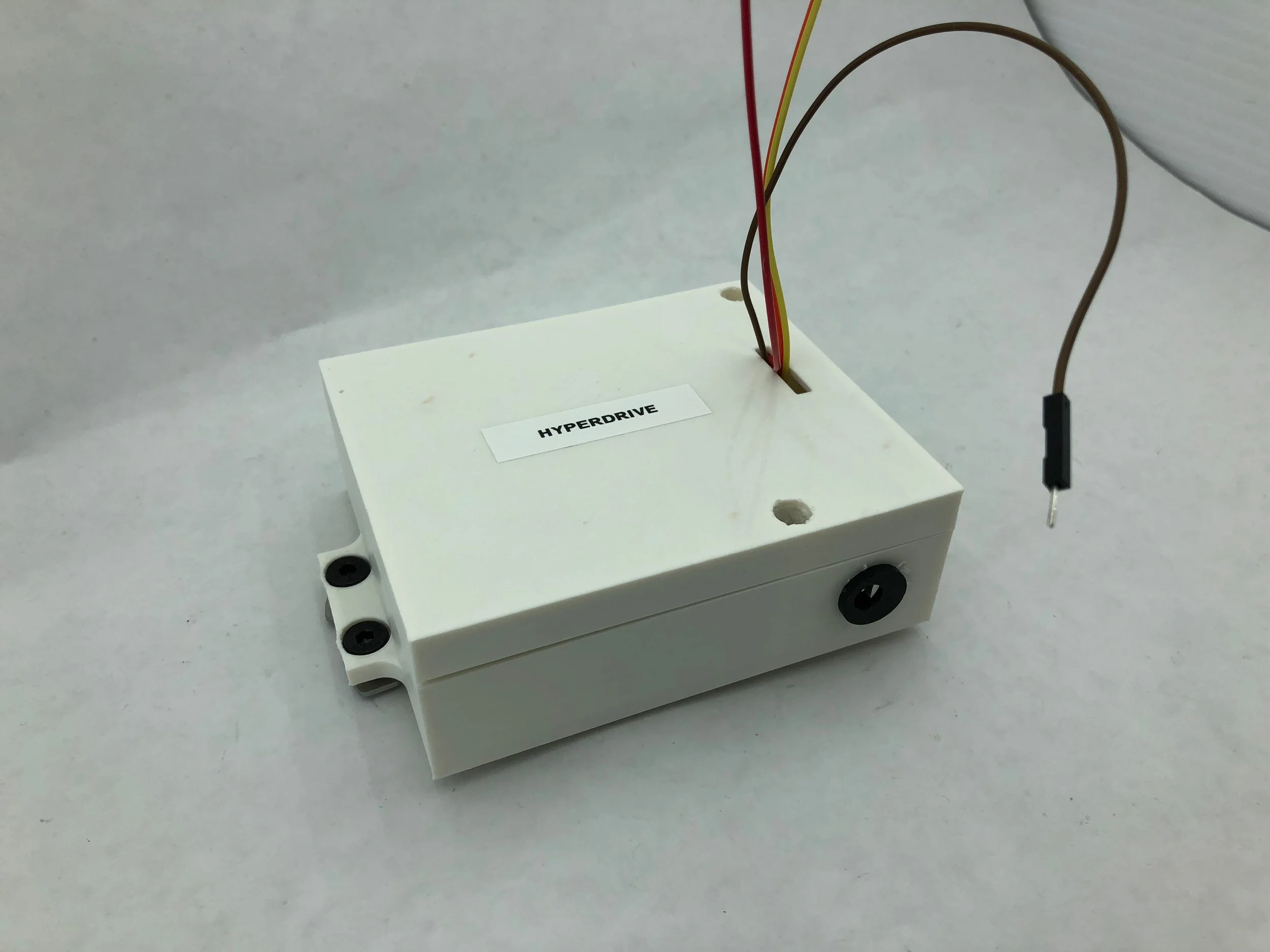
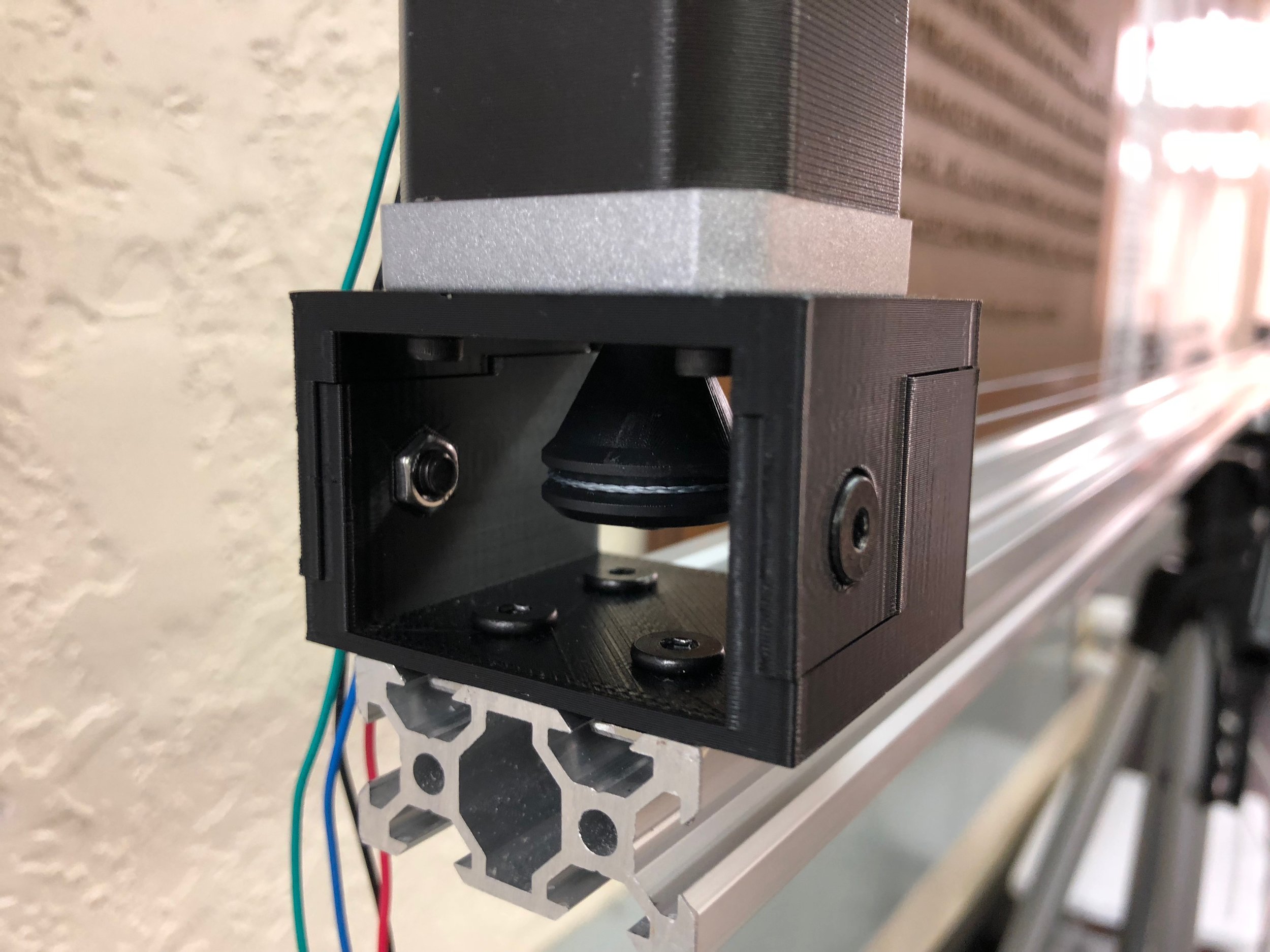
Here is what the actual part looks like when it is assembled:
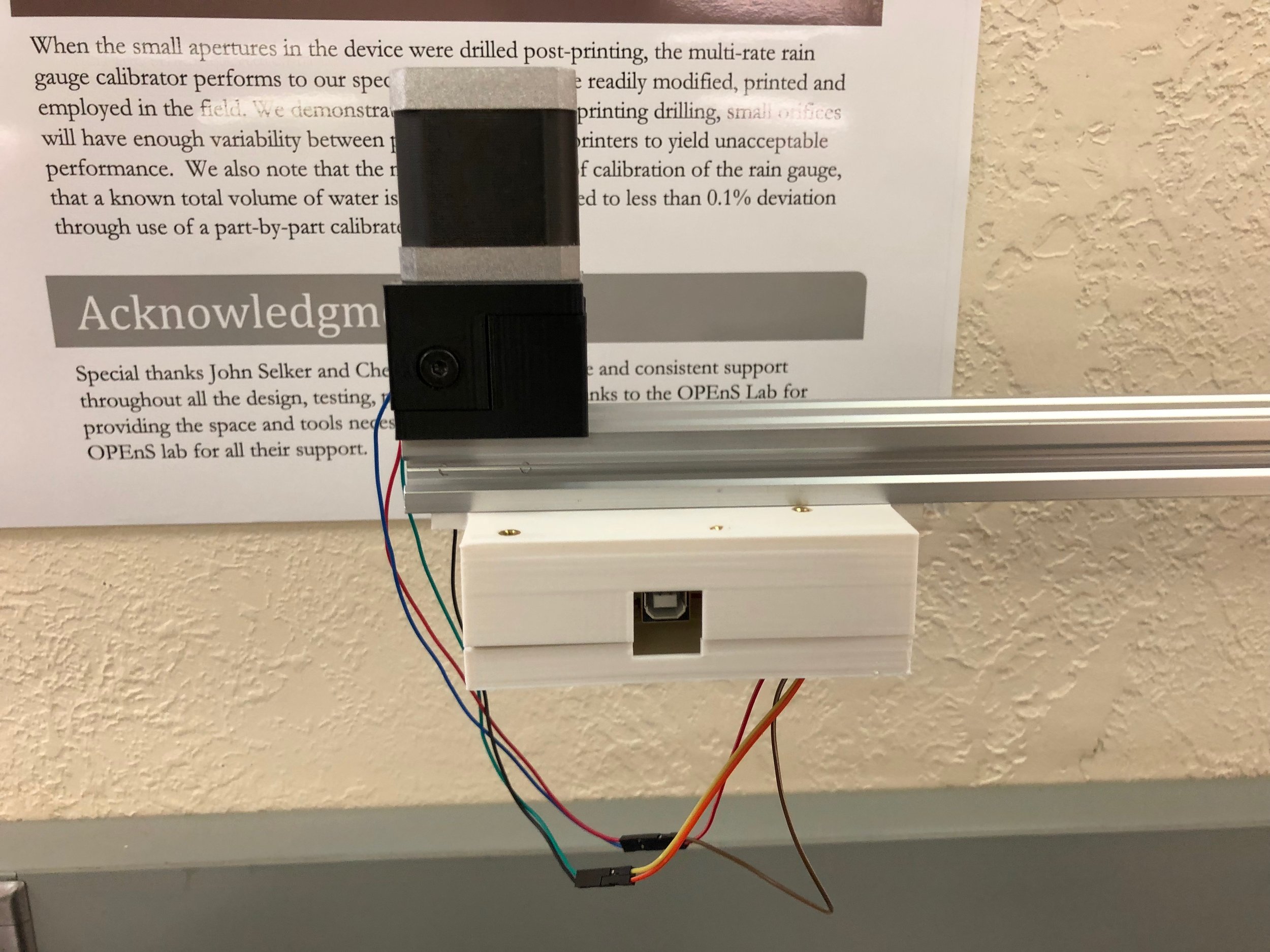
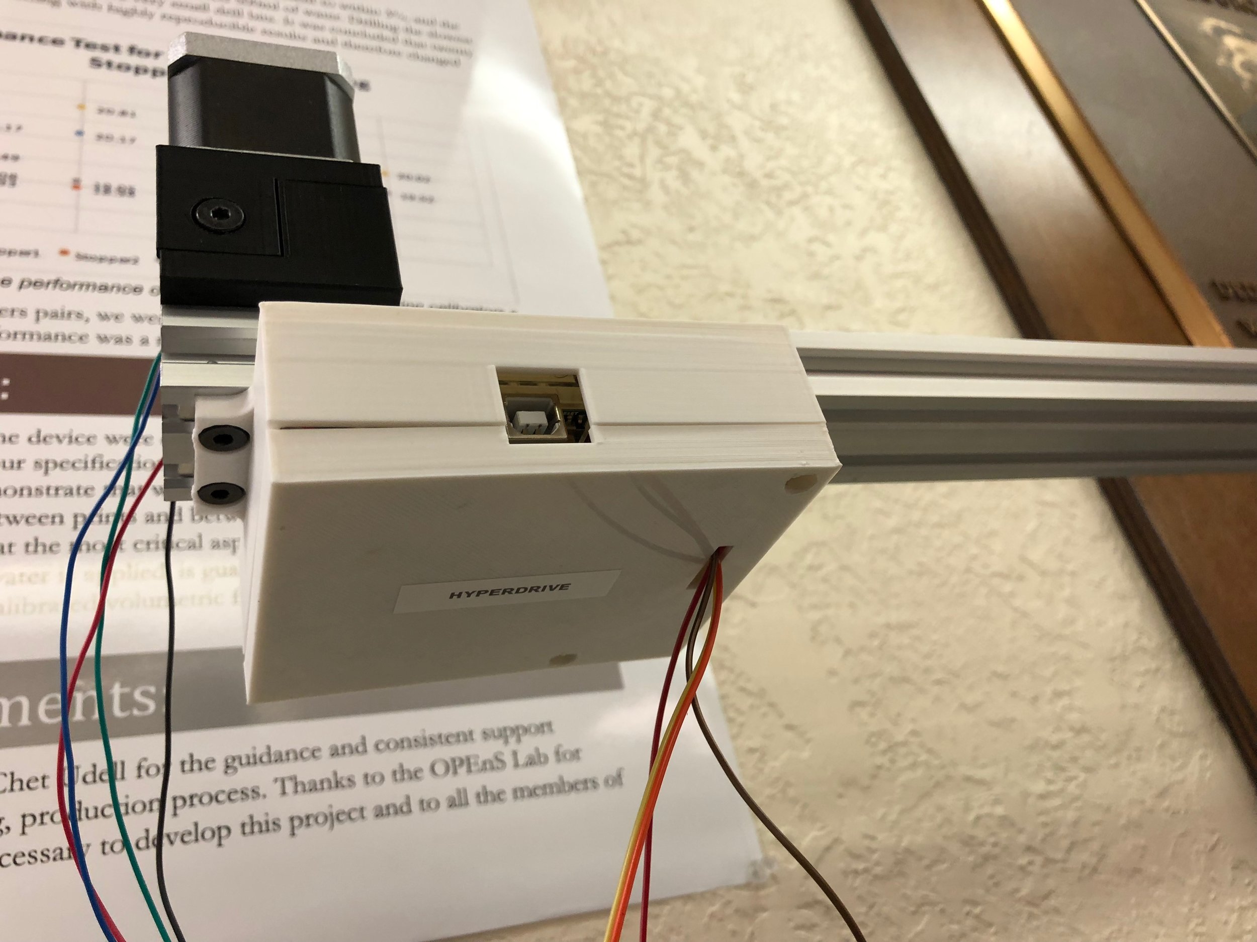
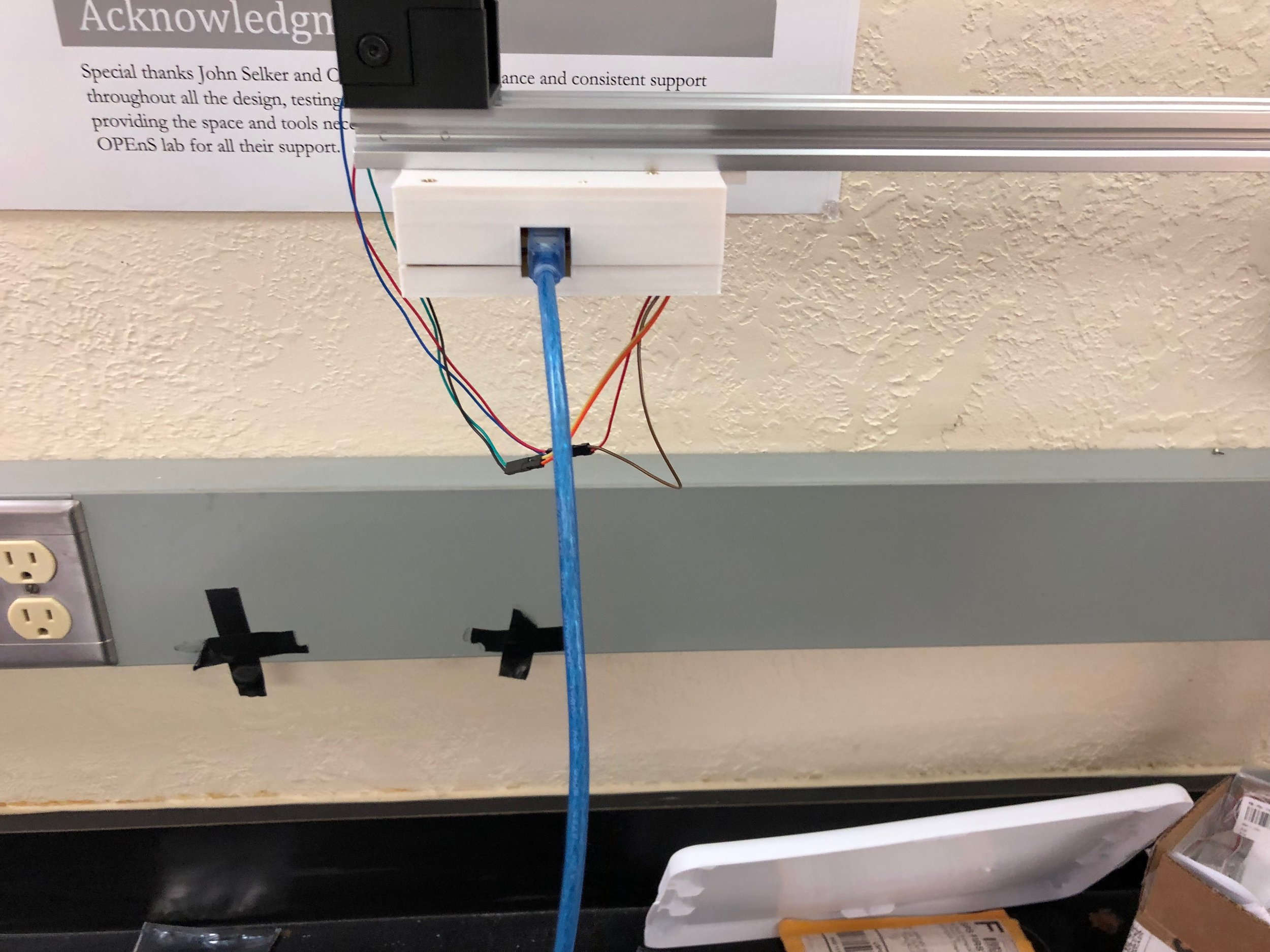
Here are some other images showing it mounted on the aluminum extrusion:
Conclusion: I am calling this whole enclosure the HyperDrive. This is because it has all the components that are driving the stepper motor. This enclosure makes it easier to move all the electronics around compared to when we had the electronics flying all over the place. Moving on to the next design, I need to make an attachment for the HyperRail to go directly on the greenhouse structure. After that is designed, then the whole system will be ready for install.
Abstract: The HyperRail is currently being controlled by the Arduino’s command line interface or CLI. But it is quite the process to change some parameters and restart the program; this whole process is not user-friendly especially if you have never used the Arduino IDE or have any coding experience. To make it easier to use I created a graphical user interface or GUI.
Objective:
Create a GUI for the HyperRail so that the system is easier to use compared to using the command line interface.
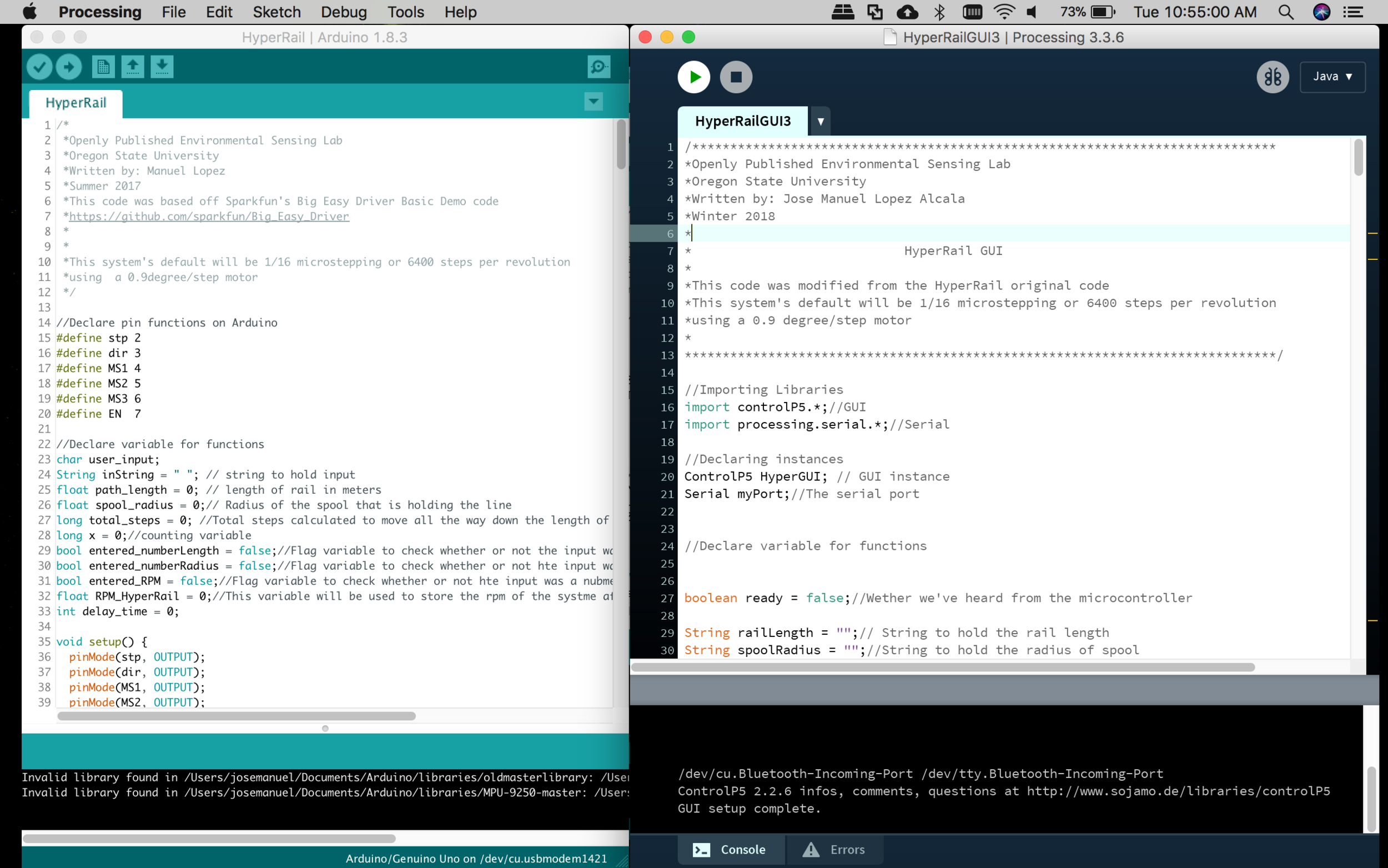
Design: For this part of the project, I am using Processing to create the GUI. This is an open source and cross-platform interface for writing code geared towards a visual processing of data and it has over 100 libraries that are readily available to make it easier for you to code. Another cool thing is that if you already use the Arduino IDE, then this IDE is going to look very familiar:
Screenshot of the two IDEs. Left is Arduino and right is Processing
This is what the current GUI for the HyperRail looks like:
Screenshot of the HyperRail GUI
I initially had the GUI controlling the Arduino using a library that the Processing software had already, but the problem came when I tried controlling the stepper motors from the GUI. What was happening is that the software does not have a delayMircroseconds() function making the controlling of the stepper motors very difficult. This is due to the fact that the function controlling the stepper motors is using microsecond-delayed pulses to move the motors. I think the reason it doesn’t have one is that it would not be able to communicate fast through the serial port. After doing more research online, I came to the conclusion that the best way of fixing this problem would be to have them be independent of each other, meaning that the Arduino would have control of the stepper motor and only be receiving triggers from the Processing. This also means that processing will be doing all the calculations to determine the total steps needed to travel the length of the HyperRail and conversion from velocity(mm/s) to RPM, this way the Arduino only is dedicated to moving the motor and not performing any calculations.
What I ended up doing is having the microcontroller send a signal to the application and then, having acknowledged that signal, have the application send the option the user chose and numbers it calculated over to the microcontroller. The microcontroller will then parse the incoming string and extrapolate the values it got from the application to then use them to move the motor at the correct speed and direction. Here is a demo of what the GUI does:
Conclusion: The GUI’s basic functions are all almost operational. At this moment I need to finish the code on the Arduino side for the parsing. After that, I will be doing some testing to see it actually works and then finish up incorporating the slider bar for quick positioning and the “Go to location” option so that the user can input specific location along the length of the rail and make the carriage go to it.
Abstract: After modifying the HyperRail’s winding system, I was able to get the line driving the carriage assembly to not wind up on itself. This used to cause the system to have very choppy movements, but now it works fine. I still need to do some testing for any slipping, but that will come next. I also fixed the deflection problem that we initially had by changing the distance between the supports. So now it should work with any length of aluminum extrusion.
Objective:
Redesign motor mount
Create modular system for any length of HyperRail
Fix deflection problem
Quick Video Update:
Descriptive Update:
Design: The old design had the tendency to break much at the little pins that were extruding from the top piece of the motor mount, and after they broke the piece would no longer be stable
Old motor mount
The next image is the new design of the motor mount. This one doesn’t have any small pieces that have the potential to break off.
New design for motor mount
Actual installed 3D printed piece
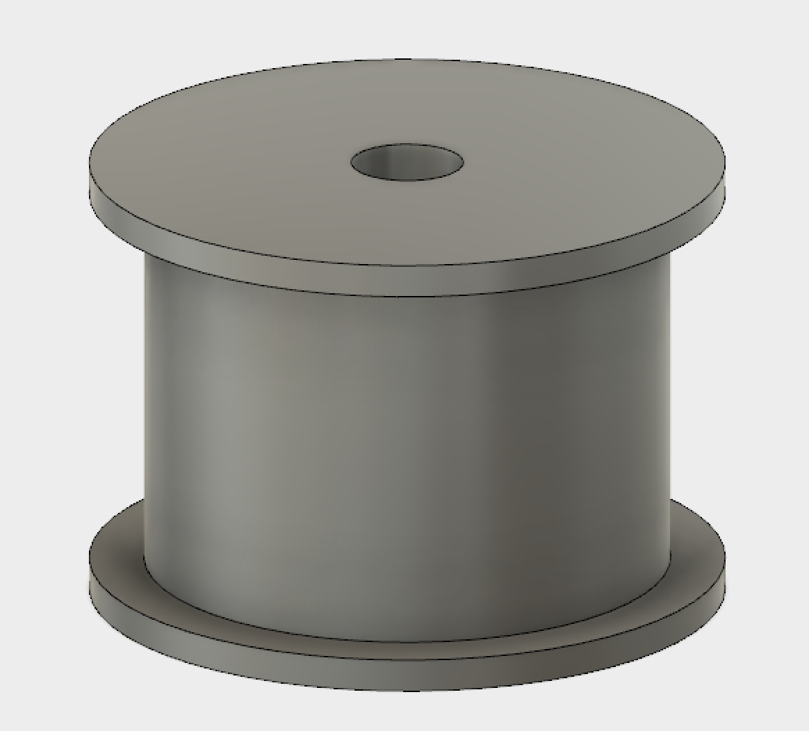
With this fixed, I then moved on to designing a better coiling system for the rail:
Old design for line spooling
New design for the line
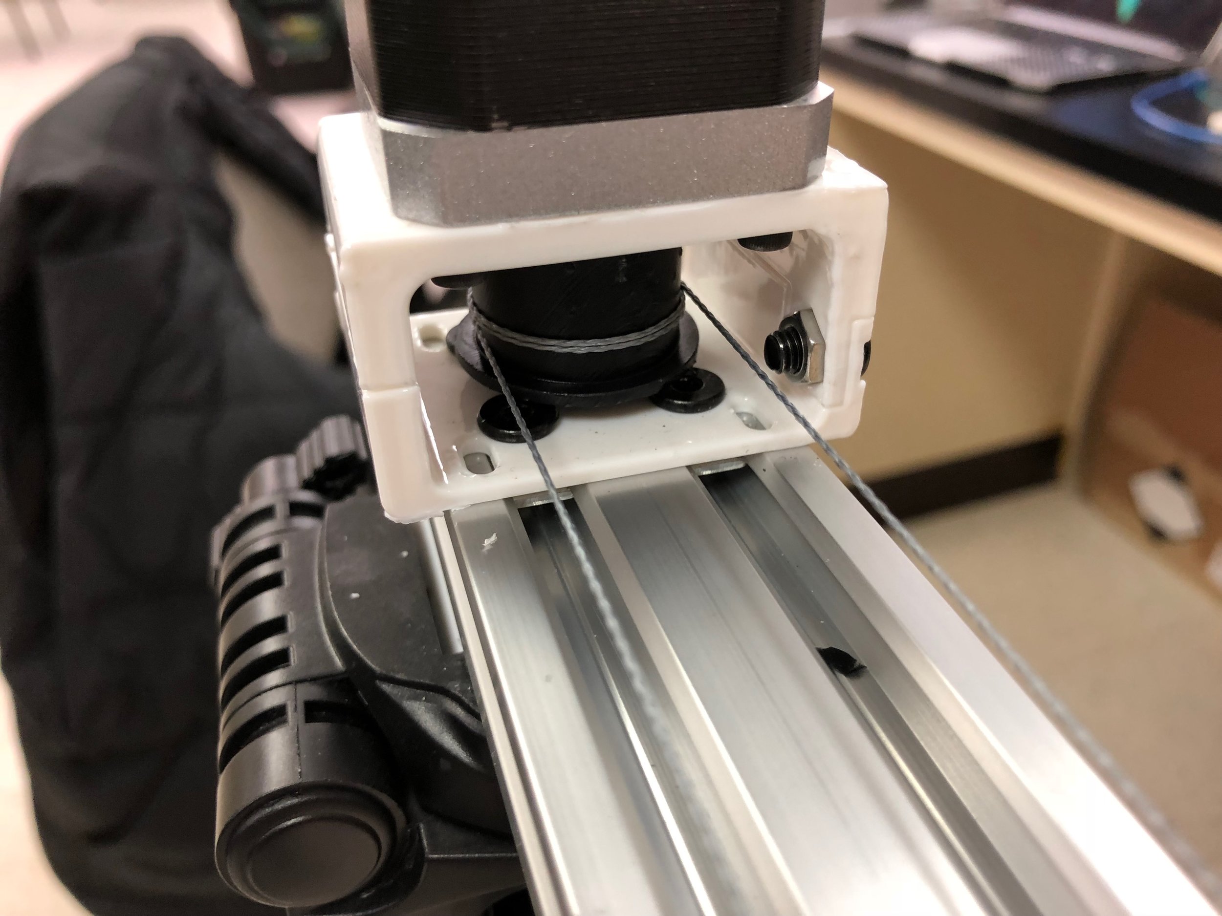
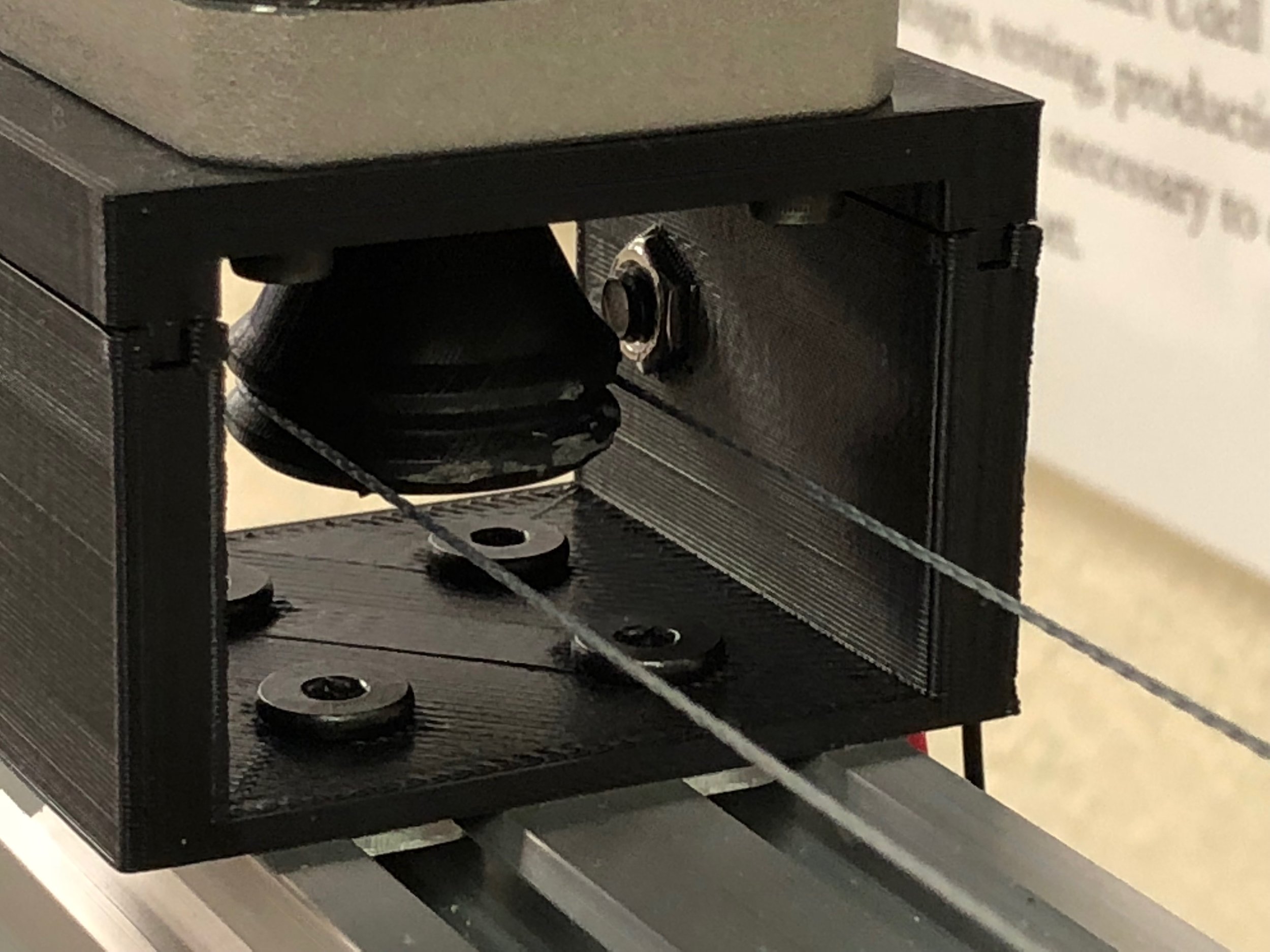
The old design actually spooled the fishing line on the plastic piece, the new one only guides the line around piece plastic piece and moves it using tension of the line.
Old prototype with only a couple of windings
New design with no windings
With this new design, the rail should work with any length of rail. I initially was testing the 1.5-meter long rail and that worked fine with the original design, but this new design worked for the 3-meter design and it looks like it would work for any size.
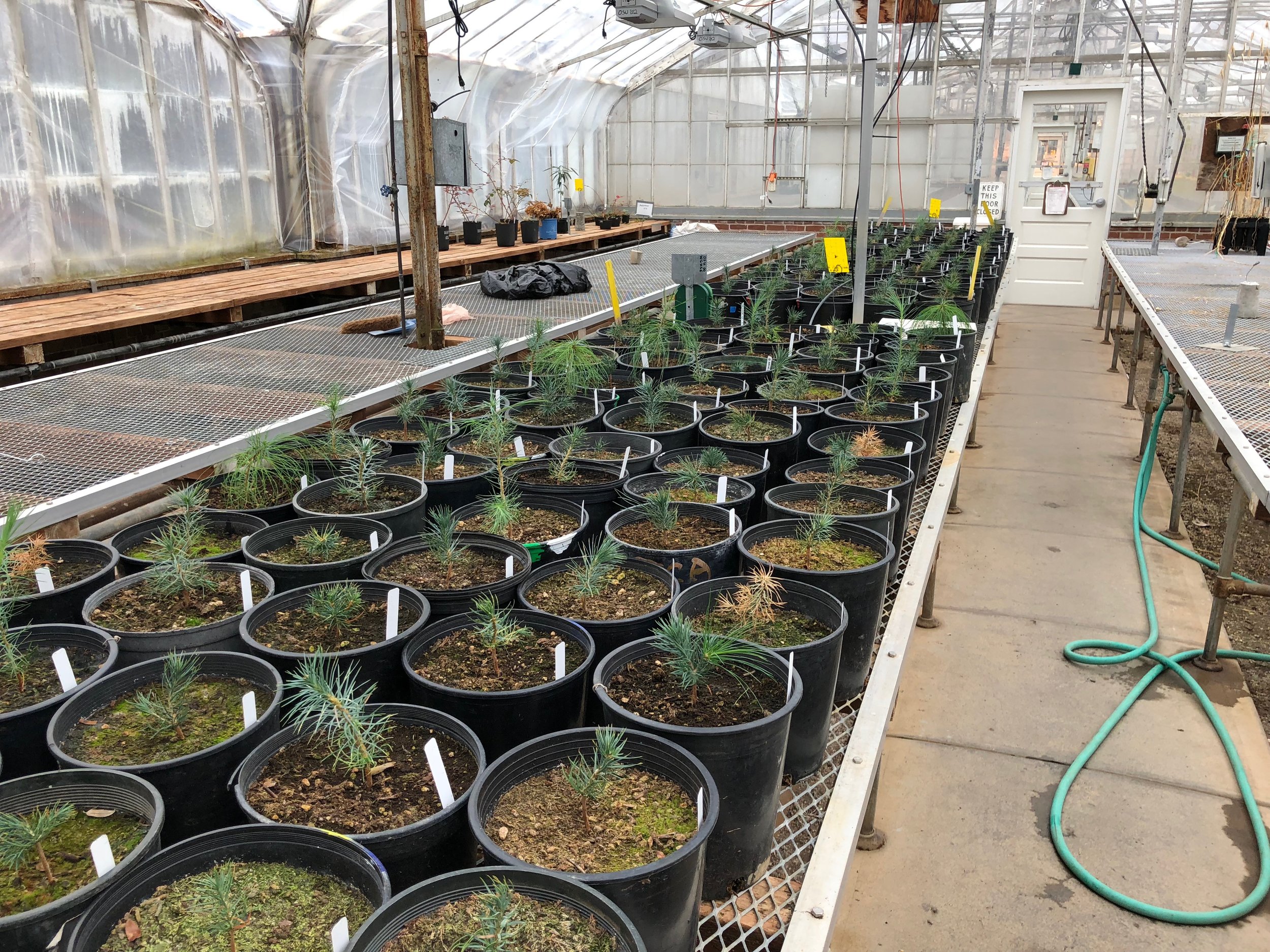
I will be testing the new design by doing an implementation of the rail in a greenhouse that is currently running some test on some plants:
Greenhouse where plants are being kept and implementation site
One advantage of setting up the HyperRail in the greenhouse is that it has a metal structure running over the plants where we can attach the rail to. This takes care of the deflection problem that we were having. The rail can have as many supports as needed and not have to worry about having any significant deflection because of this.
Metal structure where the HyperRail will be attached
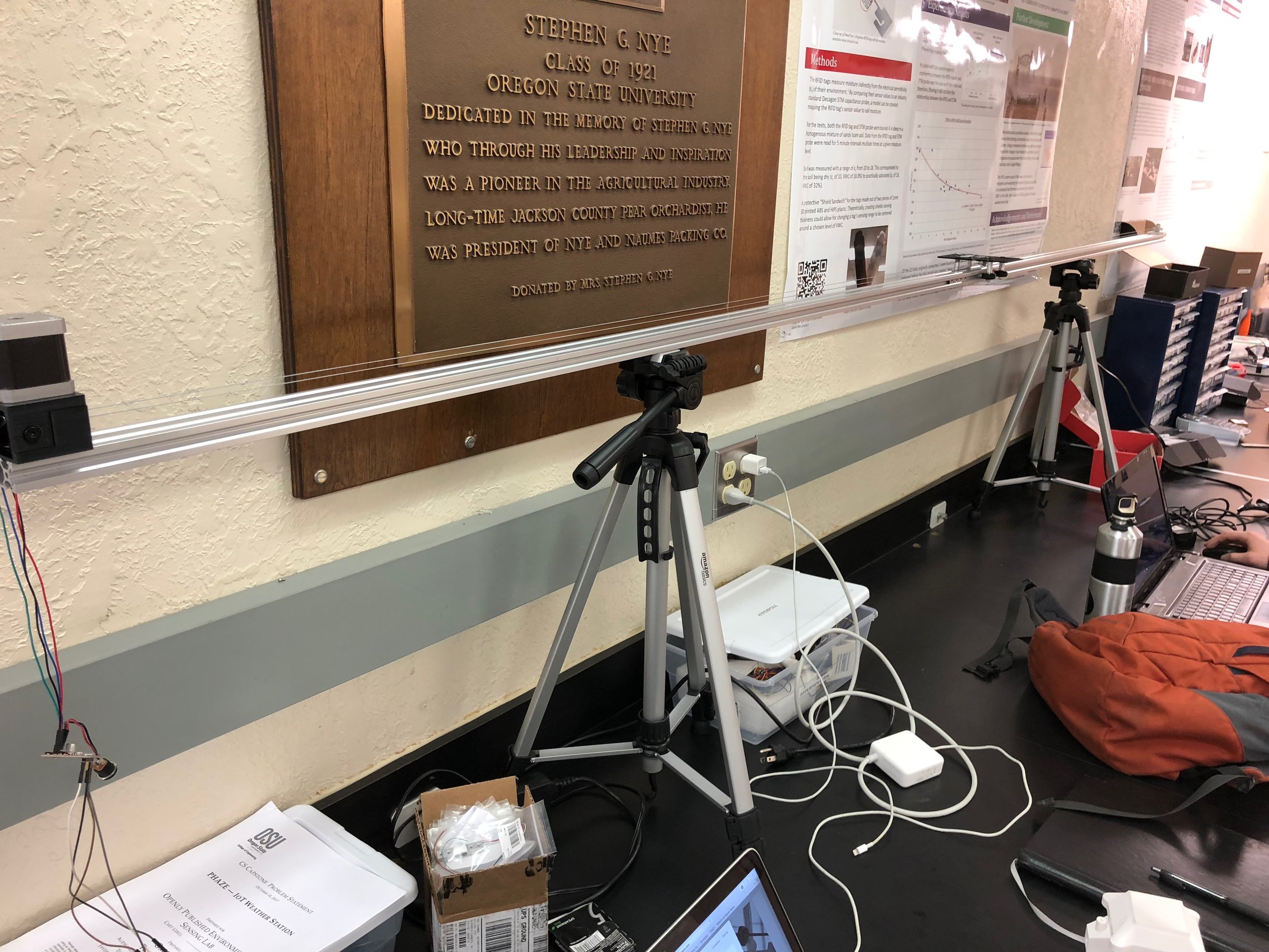
This will work if the installation site has a metal structure, but if it doesn’t have one then using the tripod system will also work. Instead of having the supports be at end of the rails, I moved them towards the center by a quarter of the distance, this way the weight is better distributed and less deflection occurs as the carriage moves across the rail.
New setup of the rail supports
Conclusion: Significant progress was done with the new designs. One future minor change is to fix the line tie. This is where the line goes gets screwed into the carriage. It keeps on breaking. In terms of hardware for the actual HyperRail, I think, it is pretty much done. The only other thing will be making the attachments for the metal structure for the greenhouse.