ETA Attachment

Abstract:  I’ve bee working on the ETA attachment and here is an update on what it looks like and where the design will go next. 

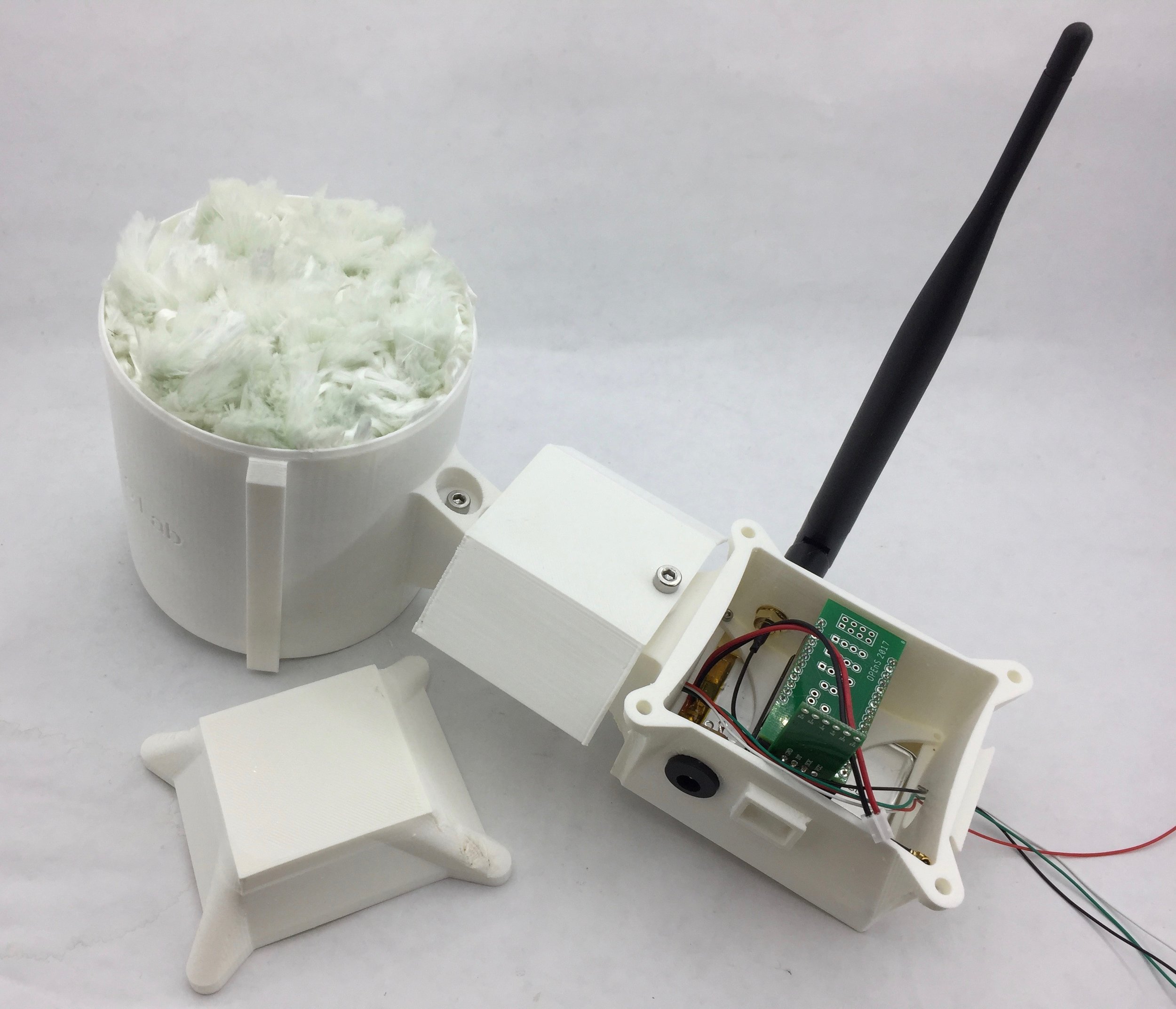
Objective: The ETA is designed to hold the two light sensors and one humidity/temp sensor. The two light sensors will make the albedo measuring system, so one has to be looking up and one straight down. The humidity/temp sensor is going right under the light sensor that is looking straight up. 

Methods: I’ve been using Fusion 360 to do the CAD and I will be 3D printing on the Fusion3 F400.

Results:

Here is the attachment piece from the sensors to the hub of the electronics. This has a slide mechanism that makes it easily detachable. This piece has to be put in first before the cap because the caps actually functions as a lock for this piece, it keeps it from sliding out in case that something bumps it. 

This is a preliminary look at what the ETA will end up looking like. This rendering is still missing the disks that will be holding the two light sensors and the humidity/temp sensor. I had to do some redesign on the base to be able to accommodate the extruding piece of the ETA attachment, but I think that this piece is solid design and I can now move on to design in the bases for the sensors. 

The bases, which will look like little disks, will hold the sensors. The one that will go on the 360 swivel will hold a light sensor on top and the humidity/temp sensor underneath. The other disk will go on the underside of the swivel, it will only hold a light sensor. 


Power Pulse Controllers Done!

Abstract: The Power Pulse Controller project has come to a conclusion. All three PPC’s have been made! Final testing is the next step to get them ready for use. 

Methods: N/A

Results: 

The following image displays a finished Power Pulse Controller. We sold one to Columbia University and have two in stock. I will get in contact with Jim Wagner to verify all the connections and test the units to make sure that they are ready.


Fully assembled Power Pulse ControllerFully assembled Power Pulse Controller

Fully assembled Power Pulse Controller


20171101_100329.jpg20171101_100329.jpg

Evaporometer 2.0 First Prototype

Abstract: Here is an update on the progress of the second versions of the Evaporimeter. We have now printed the pieces and mounted the electronics onto the 3D printed pieces. 

Objective: To inform the reader of the features and changes to the Evaporimeter design. 

Methods: I did all the CAD on Fusion360.  Here is the Assembly.

Results:

This is the CAD for the new design. 


This is the first prototype of the second version. We have to yet test the whole system, but we are getting there. There are some minor things to fix first before this design of finalized. 

This version has a barrel jack that will be used for solar power charging; this was intended for an external solar panel attachment. We are planning to integrate the solar panel into the project’s electronics, so we will be8 making a new base cap that has the solar panel in it and the electronics on the underside.

This design also gives the user access to uSD and USB by just sliding a cap off. This will be very nice when you have to get the data from the uSD card or you have to reprogram the microcontroller. 

The solar shield on this design is outdated. I want to make an octagonal version of the shied that will cover all the sides of the strain gauge. This will make it so that the heat is more evenly distributed.

Evaporometer 2.0

Abstract: Here is an update on the new evaporimeter design. This design will include the ETA sensor on it. It has not yet been designed, but the electronics base has the port for it.

Objective: This post is intended to update the reader on the new design for evaporimeter.

Methods:  I did the CAD in Fusion360. Here is the link

Results: The following CAD are the main pieces that make the new evaporimeter design. 

This is the main body that holds the battery and the electronics. The battery sits at the bottom of the case and the electronics sit on top of the battery supported by a 3D printed base.

This piece is the on that holds the electronics in place. The bottom PCB is bolted onto this piece; this one is specifically designed to bolt the Feather RTC and uSD card wing. 

This is the cap that will close the case. This is designed to be modular in height for 3D printing. Our electronics are made so that more capabilities can be added after production; this is done by stacking other shields onto the existing boards. 

This is the assembly of the case without the cover. The aluminum piece extruding from the side is the strain gauge and the black piece is a cordgrip used to pass a cable with four conductors that will be used to communicate with the light and humidity/temperature sensors.

Waterproof Evaporometer

Abstract: It was recently discovered that our transmitter is no longer sending data and that the last reading on the humidity sensor was 100%. I wonder what happened? We are now moving ahead in the design process to create a waterproof system. 

Objective: I intend to describe design considerations and current ideas that have come up to design the new enclosure for the evaporimeter base. 

Materials and Methods: 

This the new concept for the evaporimeter:


Screen Shot 2017-10-04 at 10.33.40 AM.pngScreen Shot 2017-10-04 at 10.33.40 AM.png

The idea of the new base is to have a case that consists of a main body and cap. I think it is a good idea to use a rubber gasket to seal the junction between the two. In terms of materials, I plan to keep on using ABS for the time, but using T-Glase, Bridge, or Nylon is also recommended to keep water from entering into the 3d printed case.

We also need to run some wire into the casing from the sensors on the outside. Using a coupling mechanism would be our best solution. The only problem is that our system is very small and the coupling mechanisms for that scale are very expensive, about $40 per set. Another solution that was brought up was to use rubber sheet and perforate a small hole to run the wire through. This rubber sheet will seal up against the wire and keep moisture out. We are also leaning towards using a cordgrip and using a 4 wire cable. Another solution was to find some type of waterproof ethernet cable.

Results

For now, we will be testing the cordgrip and ethernet options. These seem to be the most inexpensive options. I will also be ordering the rubber gasket to get a good seal for the base case. 

Links

Coupling Mechanism

Example Cordgrip

Rubber Seal

An Update on the HyperRail

Abstract:

The last post was about getting the HyperRail working with basic code. I have now improved the coding to give the user more control. The user can now control RPM and I have added some other functions.

Objective:

I intend to give an update on the programming of the HyperRail and new features the new code has.

Materials and Methods:

All was done using the Arduino IDE and all the code used for in this iteration can be found here.

Results:

Power Pulse Controllers

Abstract:

I have been putting together three power pulse controllers. One has already been sent out, but two more are in production. Here is a quick overview of the system specs and parts. 

Methods:

I used Fusion360 for the modeling of the PPC and to create the 2D drawings so that other people can create it more easily. 

Results:

Here is the model of the finished model on which everything was based off :

The 2D drawings (link above) contain the layout of the components on the backboard and the locations of the holes made for the components that go on outside of the enclosure. There are some extra components that are not modeled in the CAD that come with the enclosure. These are not modeled because we were not the ones who put them on there; our pieces do not interfere with these pieces.

Here is a picture of the extra pieces that come with the enclosure:


IMG_2927.jpgIMG_2927.jpg

Here are other pictures of the other two Power Pulse Controllers being built:


HyperRails are Working!

Abstract:

I have gotten the first prototype of the HyperRails working. I will be discussing the parts and setup.

Object:

This post is intended to update and inform about the progress with this project. 

Materials and Methods: 

We are using the V-slot aluminum extrusion and carriage system from openbuilds. All other parts were previously discussed in the last post about the HyperRails. These are the ones that are 3D printed in the lab. 

All of the pieces were assembled according to the CAD. This step was pretty straight forward, the one that took more time was rolling up the line on the spool and tightening it on the carriage. This took more time due to the fact that the line would tend to get loosen up and some times tangle up while coiling up on the spool.

Results and Discussion: 

Here is a video of the system in action:

The system works very well, we can see the movement of the carriage is very smooth.

Here are the links to the electrical components and code.

Test Code

Motor

Motor Driver

The main consideration for the next iteration is to make the system be able to work with all lengths. The main problem with this system is that the length of line needed for the system to work covers almost the whole surface of the coiling spool. After the line starts to overlap, the programming will have to be more complex to account for the decrease or increase of the diameter of the spool. This is the next problem to address with the next iteration. Our current system can only spool about 1.5 meters of line, and this system has to be designed to work will all lengths. One other consideration is the stretch of the line. When we were testing the system, in some cases we over extended the line and it would stretch a lot. I will need to find another fiber that has a very low stretch.

Evaporimeter System Testing

Abstract:

The system has been completed and we are now testing the components’ response to semi-realistic conditions. I say semi because it is only being tested right outside the lab. Here is what our setup looks like. 

Objective: 

With these tests that we are running, we aim to verify the functionality of the whole system. We need to make sure that the receiver and transmitter are communicating. On the receiver side, we want to see that it can run on the power supply and no connection to a computer. On the transmitter side, we want it to run on battery and be able to transmit all the data coming in from the sensors. We also intend to verify the data coming in from the sensors.

Materials and Methods:
We are going to implement an evaporimeter system right outside the lab and test the components’ response to the local enviroment. 

To simulate a rainfall we will use the OPEnS Lab rain catcher calibrator with the 20 min setting. Here is the setup:  


OPEnS Lab Evaporimeter TransmitterOPEnS Lab Evaporimeter Transmitter

OPEnS Lab Evaporimeter Transmitter

The image above displays the evaporimeter in action. 


OPEnS Calibrator SetupOPEnS Calibrator Setup

OPEnS Calibrator Setup

We set the calibrator setup above the evaporimeter and allowed it to drip 500ml of water in 20min. 

We have been testing the system and fixing anything to have it ready for deployment; this was all done during July 17th-21st. We will be doing more testing on the 24th to finalize the data collection and begin the analysis. 

One final thing to do is to print the electronics casing in white to prevent the humidity and temperature sensor from reporting incorrect data from the heat absorption of the black plastic. 

Modeling at HyperRail Speed!

Abstract:

We have decided to go with the 20x40mm V-Slot aluminum extrusion for the rail version of the hyperspectral mount. It balances strength, function, and price. Here is an update of the CAD model of the design. 

Objective:

To design the whole system to have a visual and have all parts ready for printing when the aluminum extrusion, boards, and motors come in. 

Materials and Methods:

I will be using Fusion360 to CAD the model and design all the parts that will be 3D printed. Some parts already have models from the manufacturer, so theses will only require assembly in the model.

Results:

The following are the assemblies of the parts and the designs of the parts to be 3D printed. Most of the HyperRails will be straight forward to assemble, this is because the extrusion is made for linear motion systems. The pieces that will be 3D printed will be the motor mount, string roll, extrusion connectors, tripod connectors, and rope guide. 

This is the assembly of the whole system with the major pieces.