Abstract:
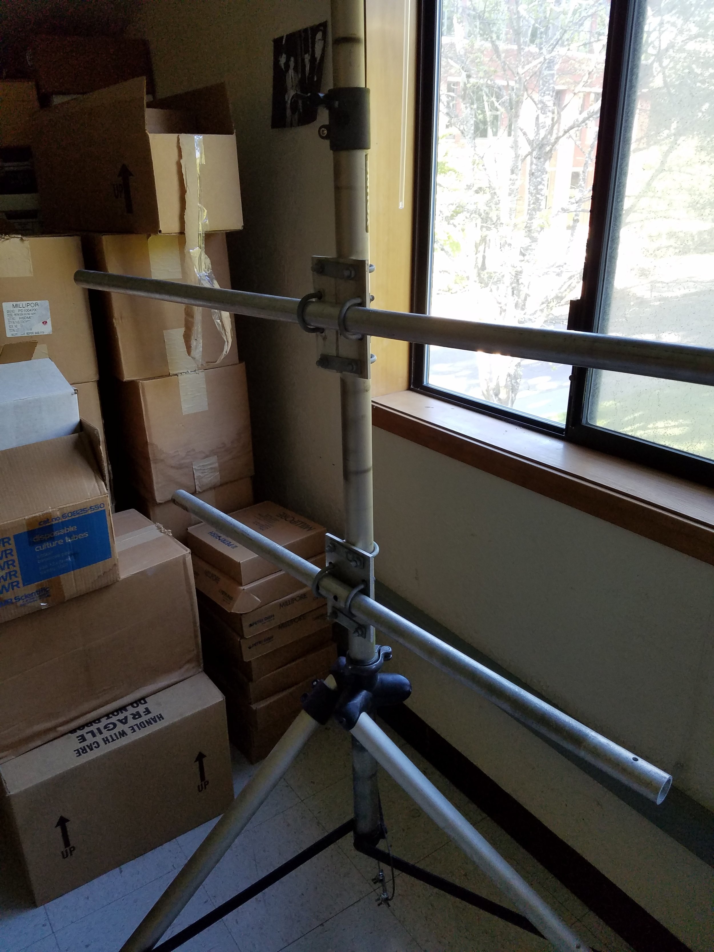
After having the first prototype of the hyperspectral camera rotating mount, it was time to start the rail version. We have aluminum extrusion in the lab, but I still need to design the carriage that will carry the camera. One important factor in this design is that it has to be modular, meaning that we have to be able to make it as small or big as needed. Having all this in mind, I set off in search for solutions that would allow me to put together this modular rail.
Objective:
To find the best material that will balance weight, modularity, and precision in order to create the rail version of this product.
Materials and Methods:
Internet searches were the main method of investigation.
Keywords:
- Aluminum Extrusion
- Rails
- Rollers
- Linear Systems
- Linear guides
Results/Discussion:
After surfing the web, I concluded on 4 potential paths to take in order to commence the build of the rail version of the hyperspectral camera rotating mechanism. The options are: linear guides, Buy Rollers or 3D print rollers.
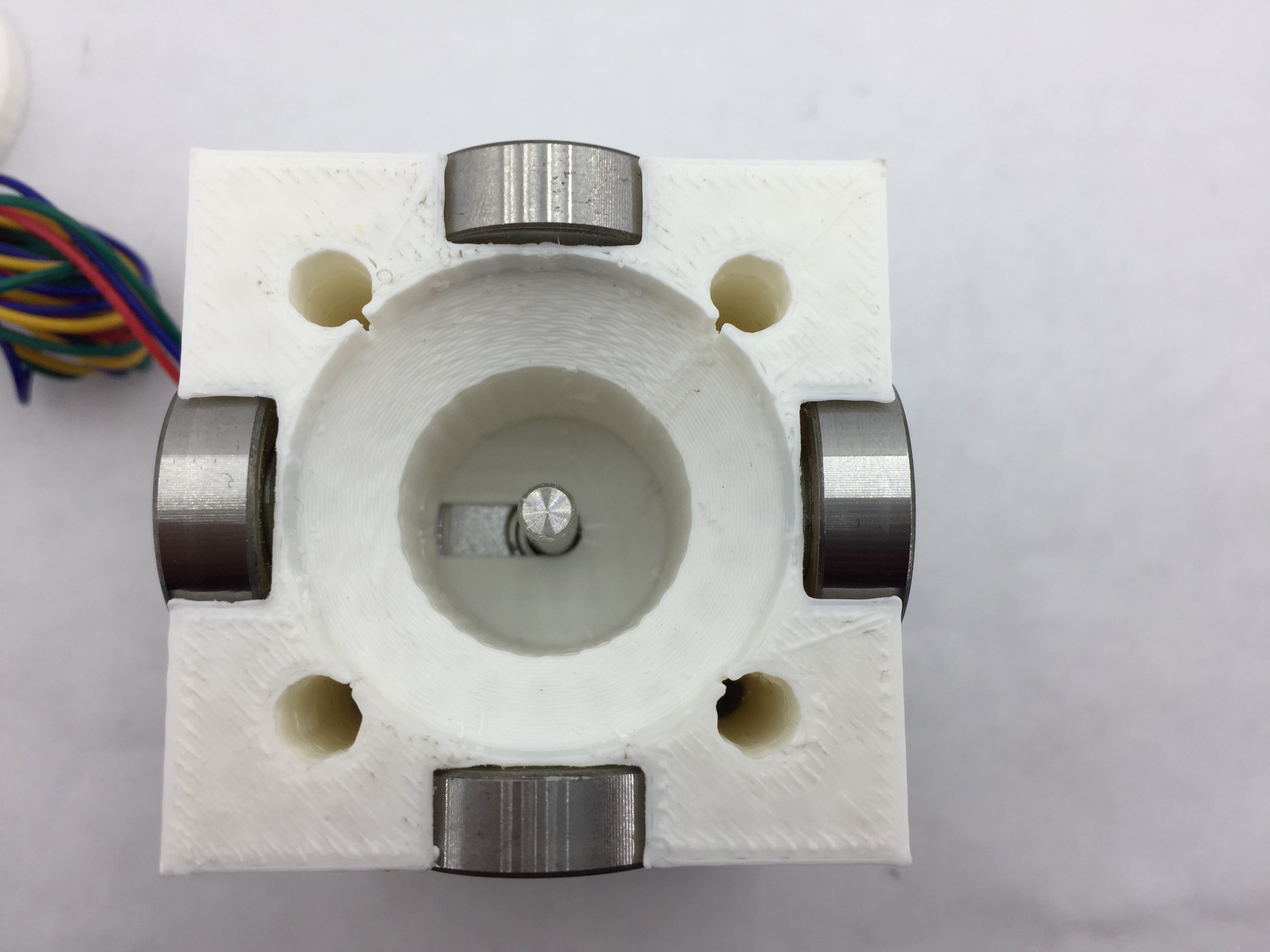
In terms of guides, the options were good but expensive. I found T, W, and V style linear guides. I easily found T and W, but I didn’t find V until the end of my search. This was due to the fact that it’s not common among the mass-produced material. The problem with the 40×40 aluminum extrusion that we have in the lab is that there exists almost nothing in terms of rollers, and the ones that do exist are expensive. I did a couple of test prints for the rollers, but I was not satisfied with the quality, therefore this was not an option.
As of right now, I think that going with the V style guides is our best option. This is because they are the most economical of all and they are specifically manufactured for linear motion systems. The price is about $6/m, compared to the others this is cheap! The other materials were coming in at $825.82/m, $301.72/m, and $65.55/m; this is for the w and t style rails.
The website that carries the V style guides also has the necessary components to mount the rails onto the aluminum extrusion and has the plate for the carriage. This way we can get everything from the same vendor and at a reasonable price.
Pictures:
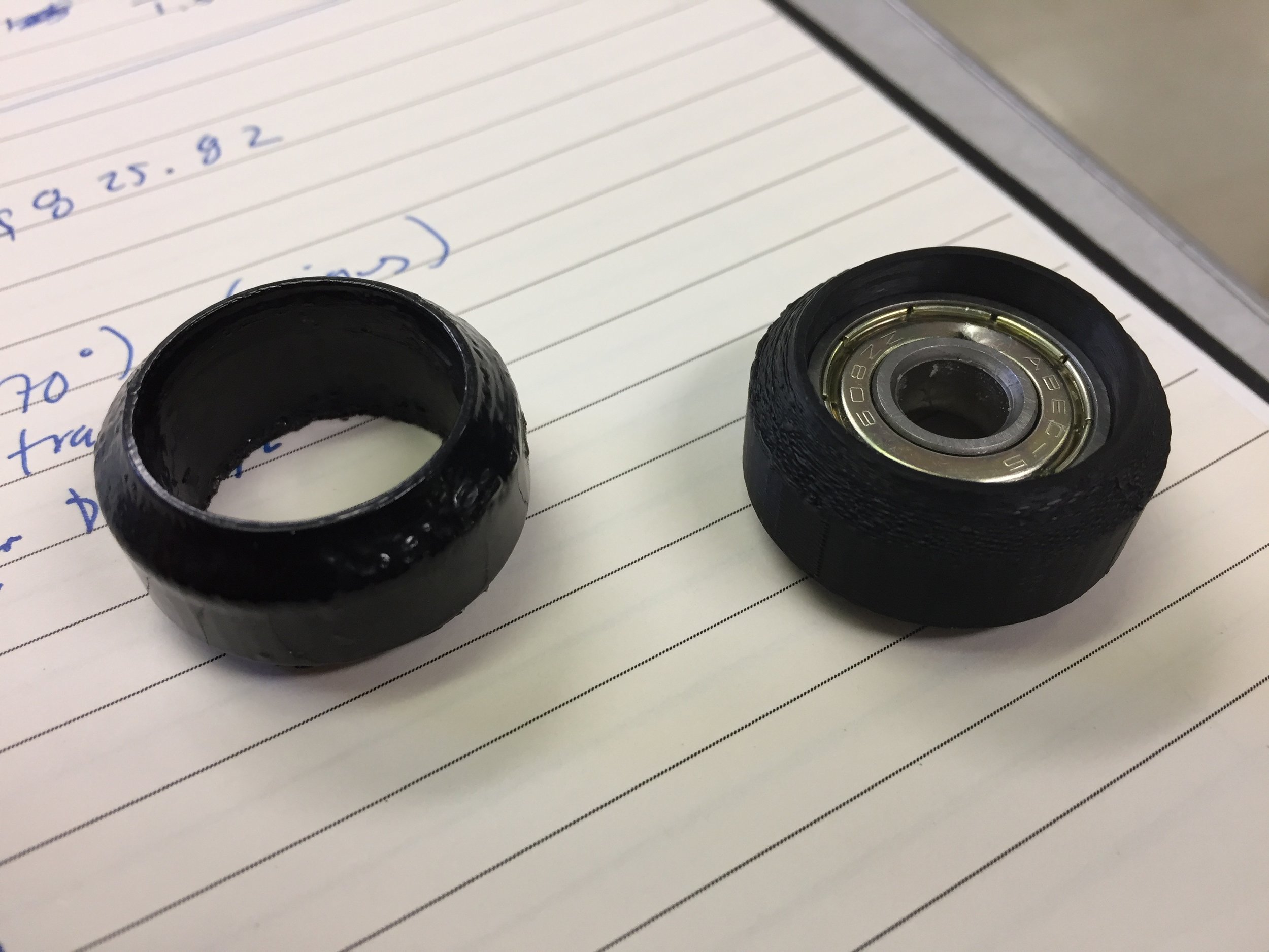
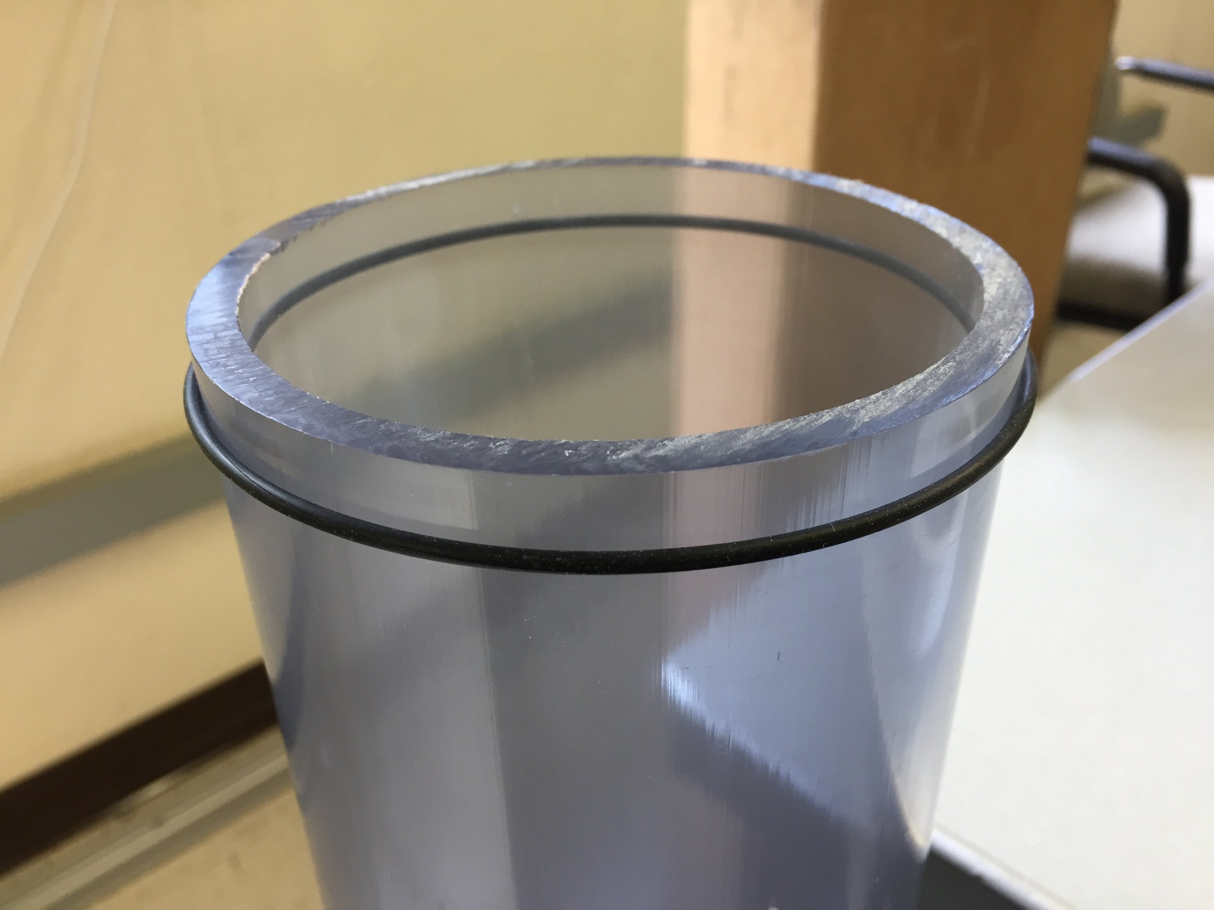
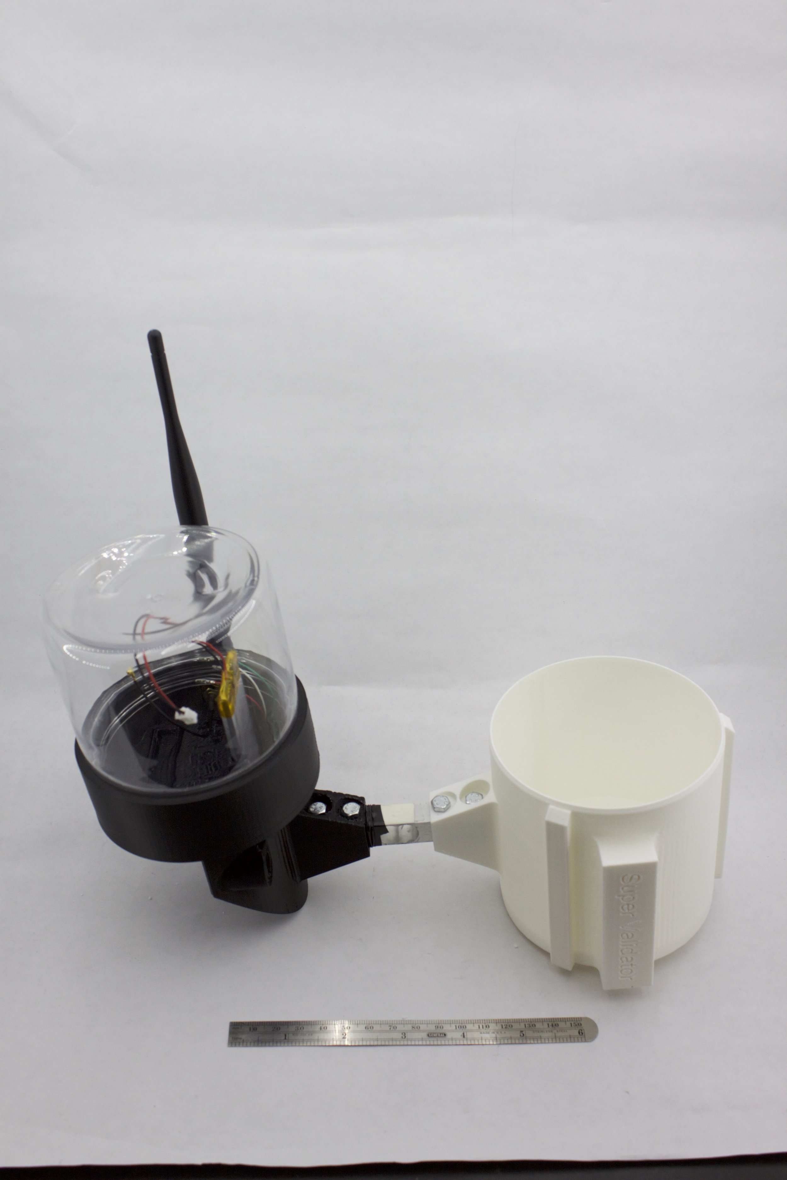
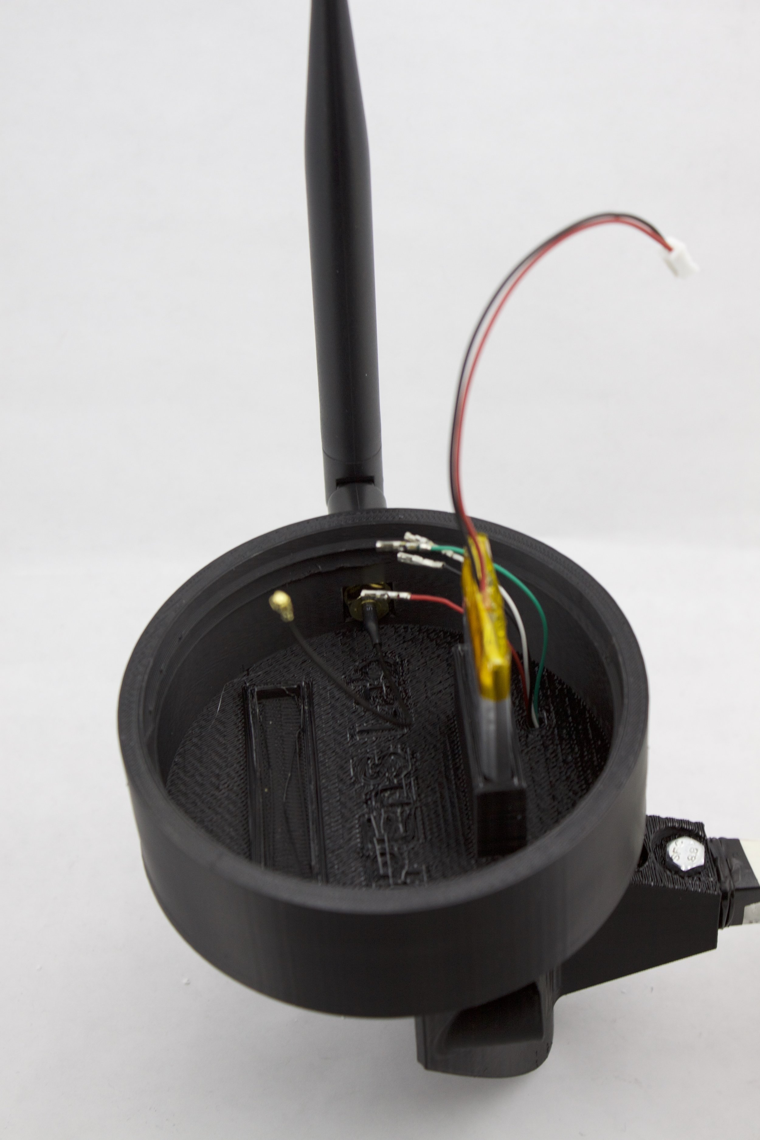
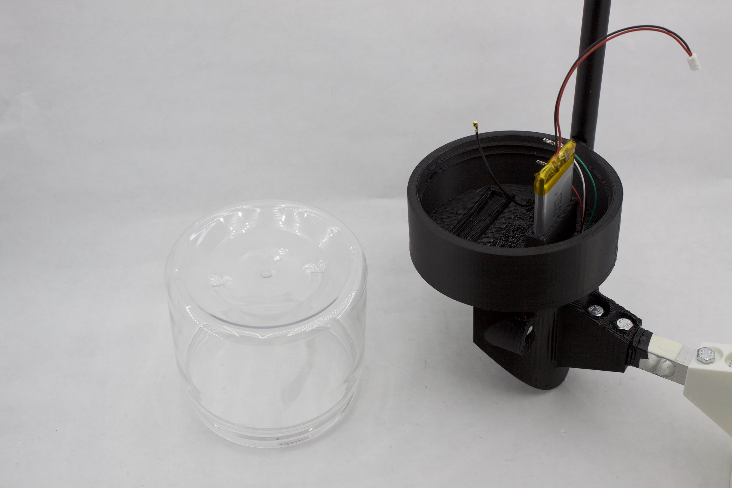
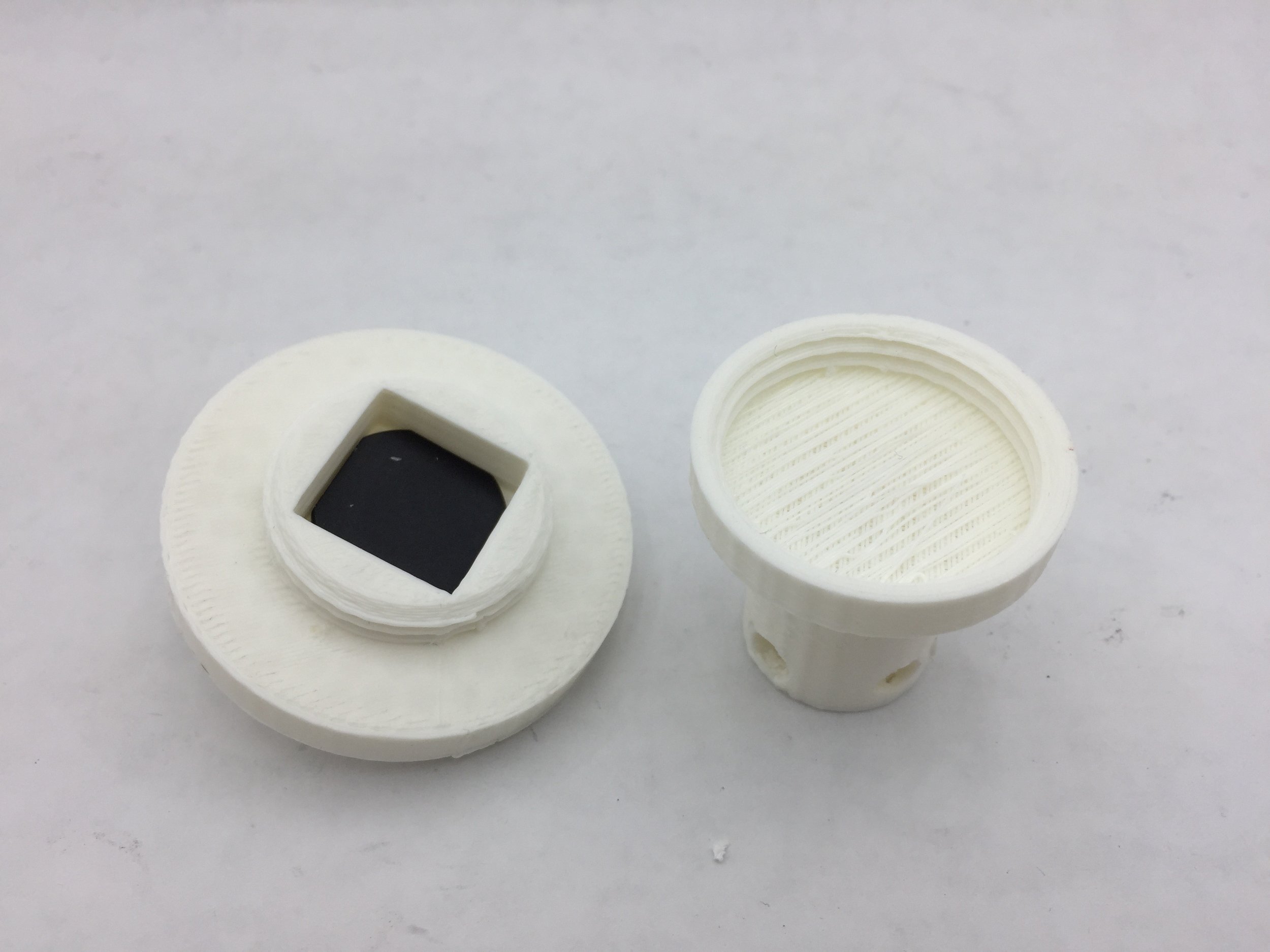
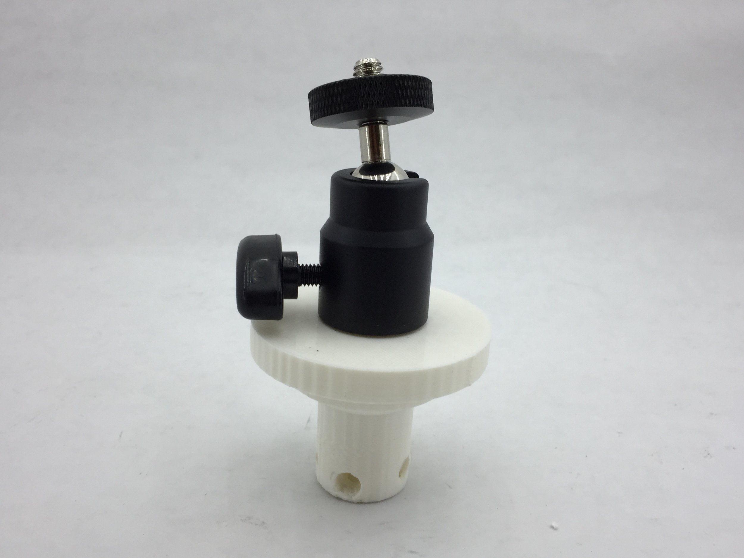
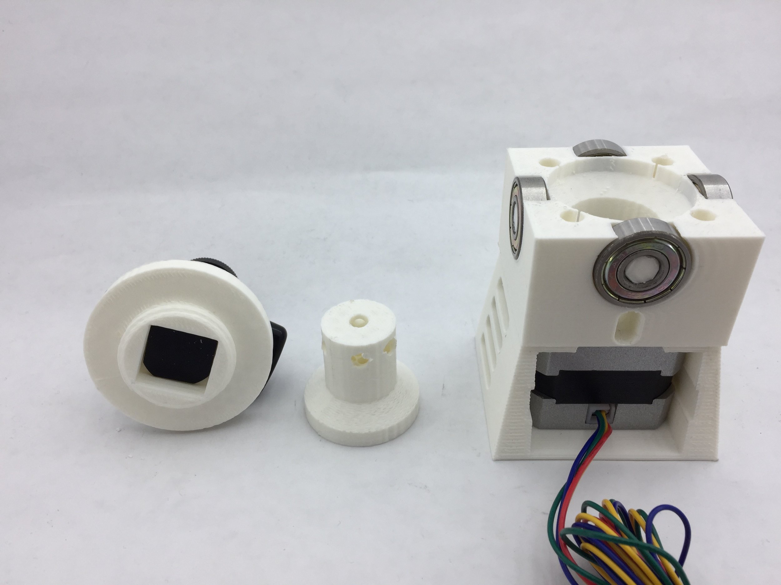
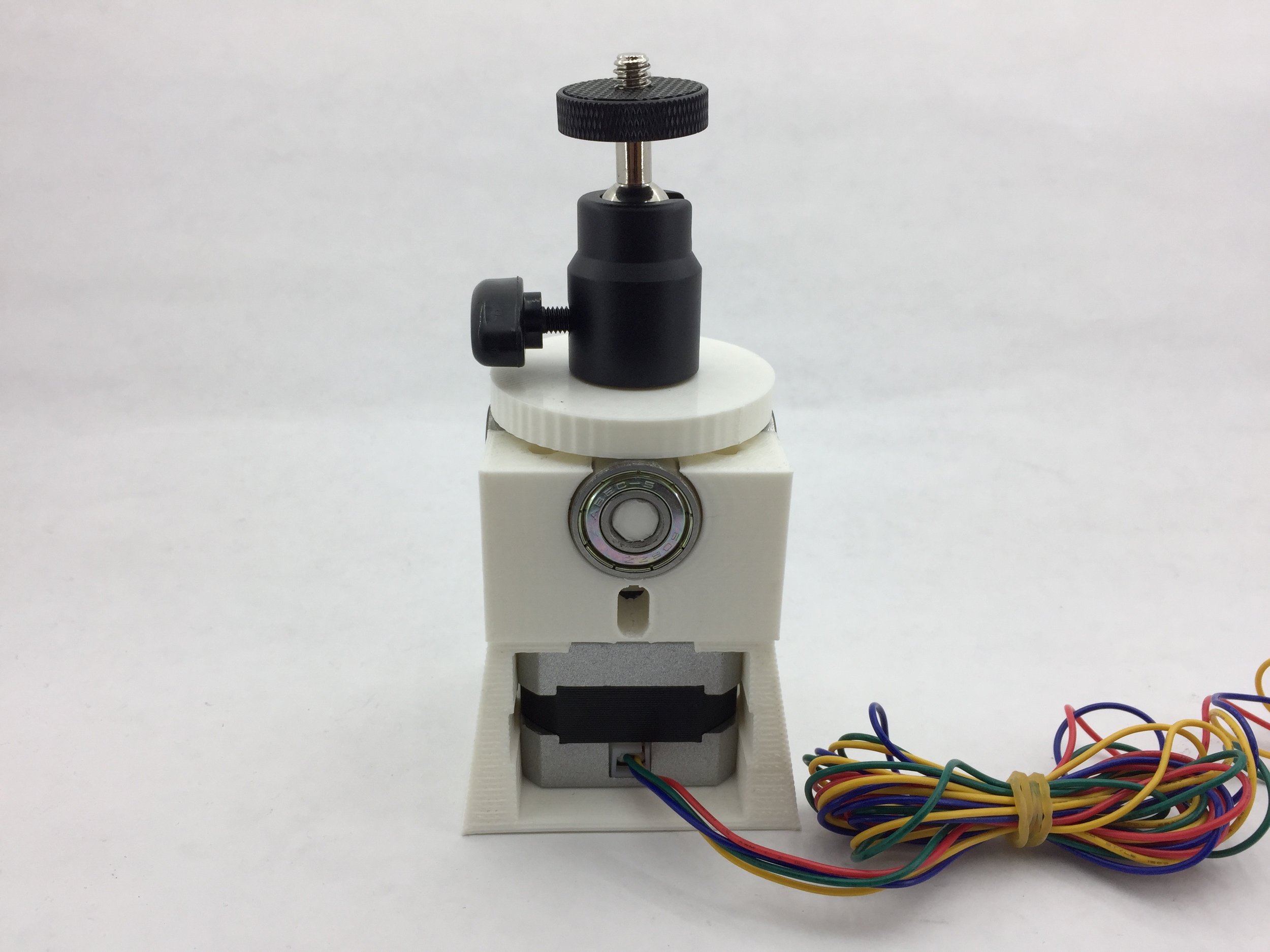
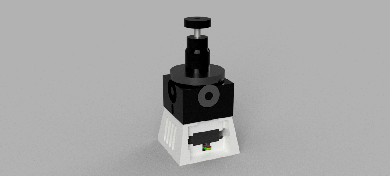
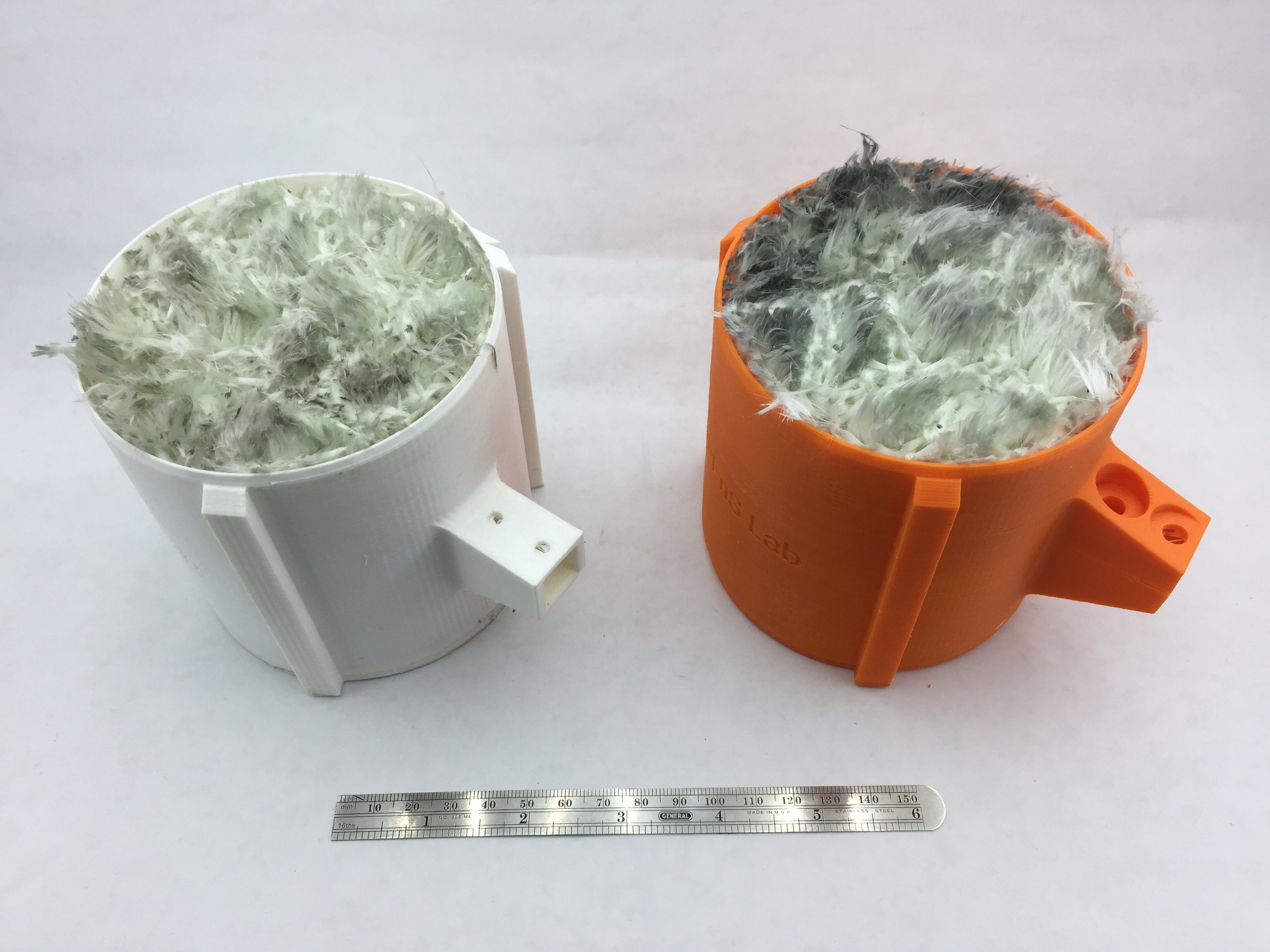
3D printed rollers
Links: