Interfacing with the ROCKBLOCK+ SatCom Module

Author: Kamron Ebrahimi

What is ROCKBLOCK?

ROCKBLOCK is an out of the box satellite communication module manufactured by Rock7. The device is constructed to interface with embedded microprocessors such as Arduino’s and Raspberry Pi’s. What makes the ROCKBLOCK such an incredible device (and also an appealing tool for the SlideSentinel project) is the fact that it can send Short-Burst Data (SBD) through the Iridium Satellite constellation, an aggregate of 66 active satellites used for worldwide voice and data communication. This means that projects using the ROCKBLOCK satcom module can send and receive data from a basestation from just about anywhere on the surface of the Earth that is exposed to the open sky.

Slide Sentinel Use Cases


ROCKBLOCK+ placed outdoors for signal testing.ROCKBLOCK+ placed outdoors for signal testing.

ROCKBLOCK+ placed outdoors for signal testing.

Due to the remote nature of the SlideSentinel deployments and potential weather hazards, the team has opted to use the ROCKBLOCK module for sending data from the base node to servers where it can be further processed and recorded via Google spreadsheets.

ROCKBLOCK+ Interface

IMG_5101.jpgIMG_5101.jpg

The ROCKBLOCK+ exposes a 7 wire interface

  • GND
  • 9-30 VDC input
  • RS232 TX
  • RS232 RX
  • On/Off control (sleep pin)
  • Ring Alert Indicator
  • Network Availability

For simple use cases involving synchronously sending data, the only needed pins are the RX and TX lines, however the On/Off control pin, Ring Alert Indicator, Network Availability offer useful functionality which merit discussion. The ROCKBLOCK+ has an internal super-capacitor which requires roughly 10 seconds to charge. Once charged the module can begin sending data. If you are constructing a time critical application the On/Off control pin puts the module into a “sleep” mode, in which minimal power is consumed to maintain the super-capacitors charge. This allows the module to wake up quickly (perhaps due to an interrupt) and skip the 10 second capacitor charge wait before sending data.

The ring alert indicator is an active low output from the ROCKBLOCK+. When the voltage on the pin goes low there is a in incoming message in the MT queue which can be read by the module. This pin is useful for bidirectional communication with the module.

Finally the ROCKBLOCK+ presents an active low network availability pin. When the ROCKBLOCK+ module is on, the device periodically polls for an available Iridium satellite connection. If such a connection is found there is a high likelihood that data can be sent and received by the device and the network availability pin will go low.

For the official developer documentation on the ROCKBLOCK module follow this link.

Talking the ROCKBLOCK+’s Language, RS232

All outputs and inputs to the ROCKBLOCK+ must present RS232 voltage levels. Thus if communicating with the module with a TTL device an RS232 level shifter must be used. In the case of the SlideSentinel project the Adafruit Feather is used to send AT commands to the module. For testing the module on a breadboard we used the MAX3232 IC, which convert 3.3 volt TTL to RS232 and has two line drives and receivers. This linked article provides a concise explanation on the RS232 standard.

In order to receive the network availability, On/Off, and ring indicator signals an RS232 level shifter with at least four receive lines is required. For the SlideSentinel PCB interface to the ROCKBLOCK+ we decided to use the MAX3242 IC which presents 5 receive lines and 3 transmission lines.

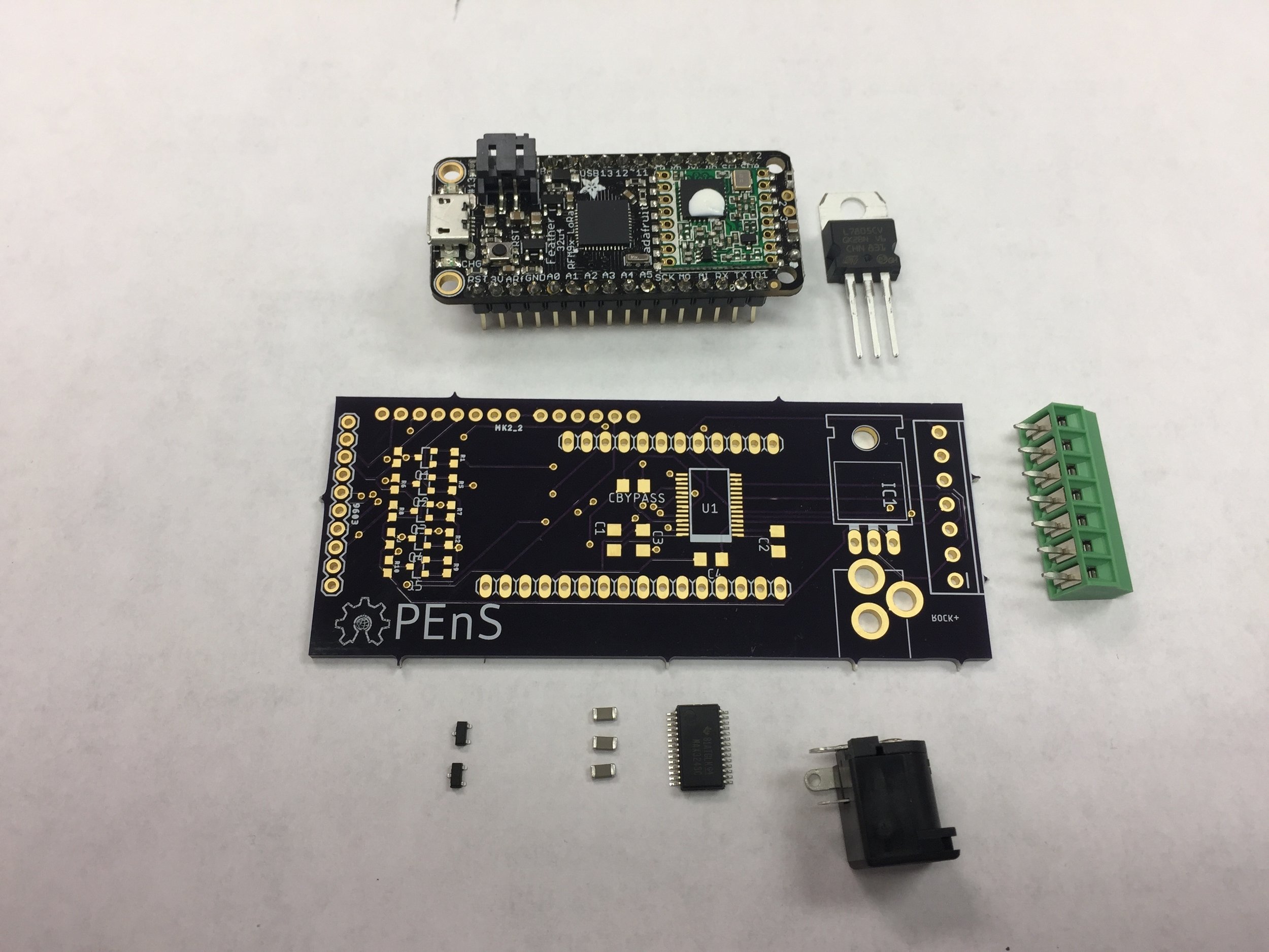
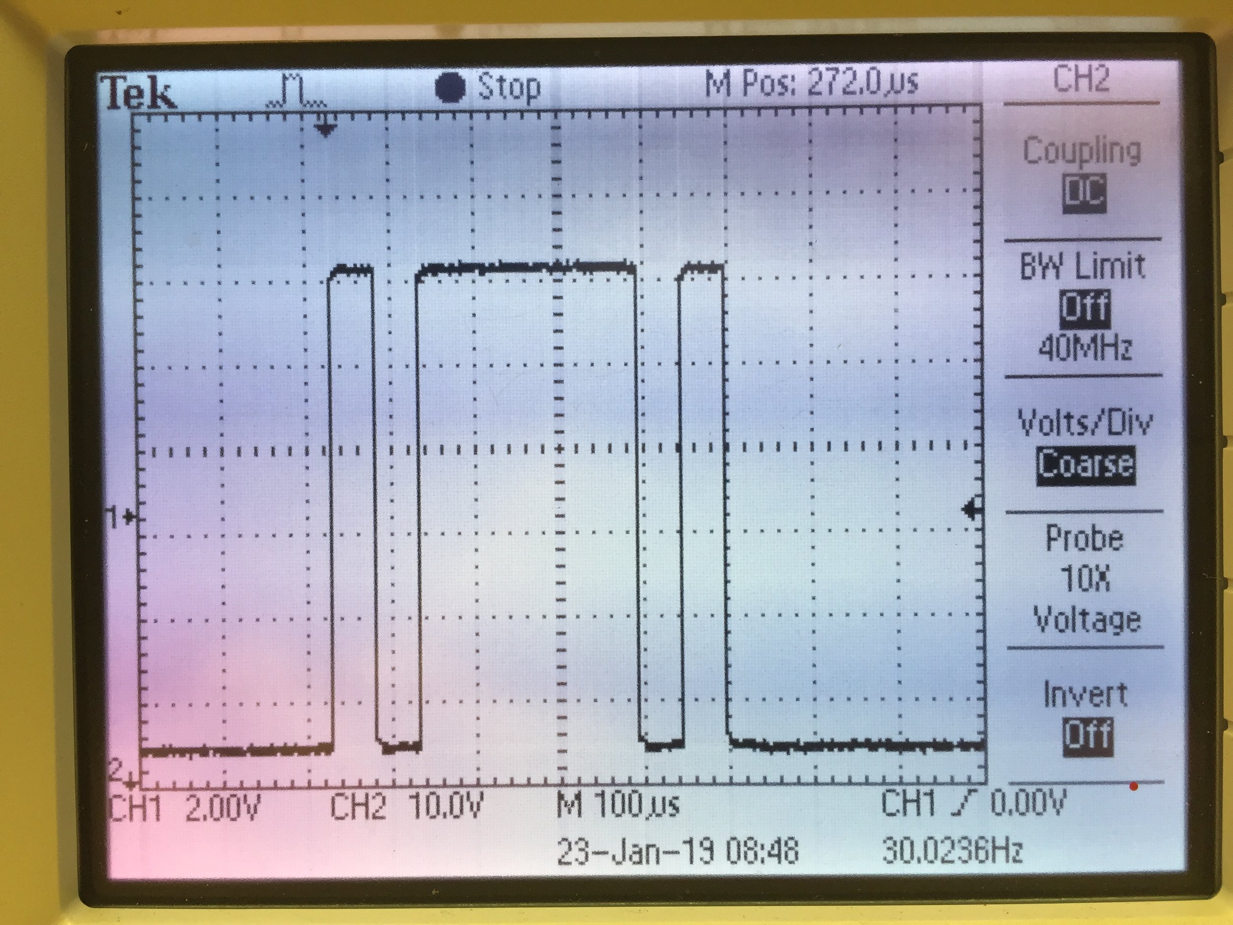
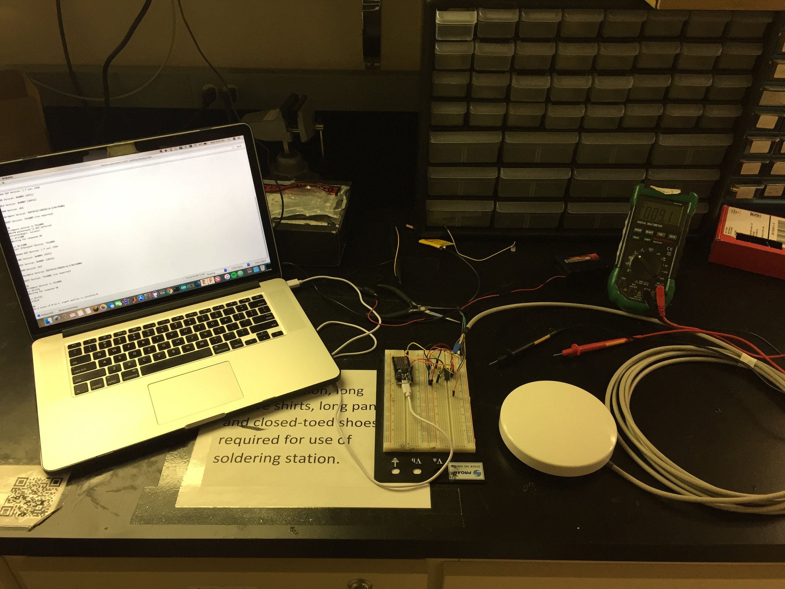
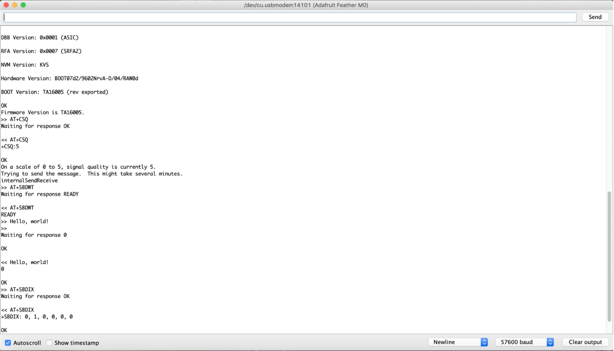
With the RS232 interface configured the last step is sending AT commands to the module. The IridiumSBD is a convenient library for interfacing with the modem. Below are three photos depicting the a serial output from an Arduino script which communicates with the ROCKBLOCK+, a picture of the probed RS232 UART signals between the Arduino and ROCKBLOCK and the PCB designed to interface with the module for the Adafruit Feather. The Arduino script asks the module for its firmware version, then is asks the module for a number between 0-5 indicating signal strength and finally sends an AT command which transmits the string “Hello World.”
90% of effort in the last 10%

Author: Lars Larson

The devil is in the details, and the process of ensuring stable operation has been full of them.

Issues during recent deployment

After multiple attempts with intermittent data transmission, it’s time to rebuild the nRF protocol. Some observations from the last deployment on 22 January 2019:

  • Range tests (simple call-response between nodes) on site are robust beyond 400 meters, when the required range is only around 150 meters.
  • Boosting the power with radio.setPALevel_MAX is essential to achieve desired range
  • The entire sequence only works intermittently from HyperRail hub to the sensor package, back to the hub, and forwarded to the ethernet base station at the main office.
  • The larger distance between the greenhouse and the ethernet hub is the component that is dropping data packets

Next Steps:

  1. The physical range constrained by the hardware does not appear to be the issue with the current nRF chips (Itead nRF24L01 + PA + LNA). Therefore, the code must be modified to address potential timing/network updating issues
  2. I will work with the Loom team this week to “Loomify” the nRF protocol by swapping in the Loom functions for each of the 3 nodes.
  3. Before next deployment, the system will be tested by recreating the field conditions to the best of our ability

On the bright side:

Around 50 data points were successfully sent, and the hardware was all very stable, especially the HyperRail system. The end is in sight!

Access eGreenhouse data stream live:

eGreenhouse Google Sheets

Smarter Rock

By: Alicia Veach

Smart Rock Rev 2 is making headway as the new staff catch up with the project. New design criteria is being laid out and tasks are being distributed. The two task categories are electrical and mechanical. On the electrical side, an optical flow sensor has been purchased to test and see about possible use. The sensor will be used for water flow rates. Reed switches are coming in to be tested as an option. The Smart Rock would ideally be off for the majority of the time while deployed to conserve battery. A reed switch can be used to turn on the rock, connect, and collect data. On the mechanical side, the rock will now be horizontal rather than vertical and more water-tight than previously. OPEnS House is coming up soon and a poster is being put together.

Update on the Evaporometer

Author: James Yang

Abstract: An update on where the Evaporometer is and addressing the issues as well as what the future plans are for the project.

Temperature Compensation Issues:

There are a few things that we are in the process of implementing within the project. To start, temperature data collected last summer had readings that spiked from 26 degrees to 700+ degrees resulting in huge inaccuracies. The reason is because the previous Op Amp would fluctuate in mass when the temperature changed. To fix this issue, we are replacing the previous OP amp with an INA125P to hopefully reduce temperature compensation problems.

Sustainability:

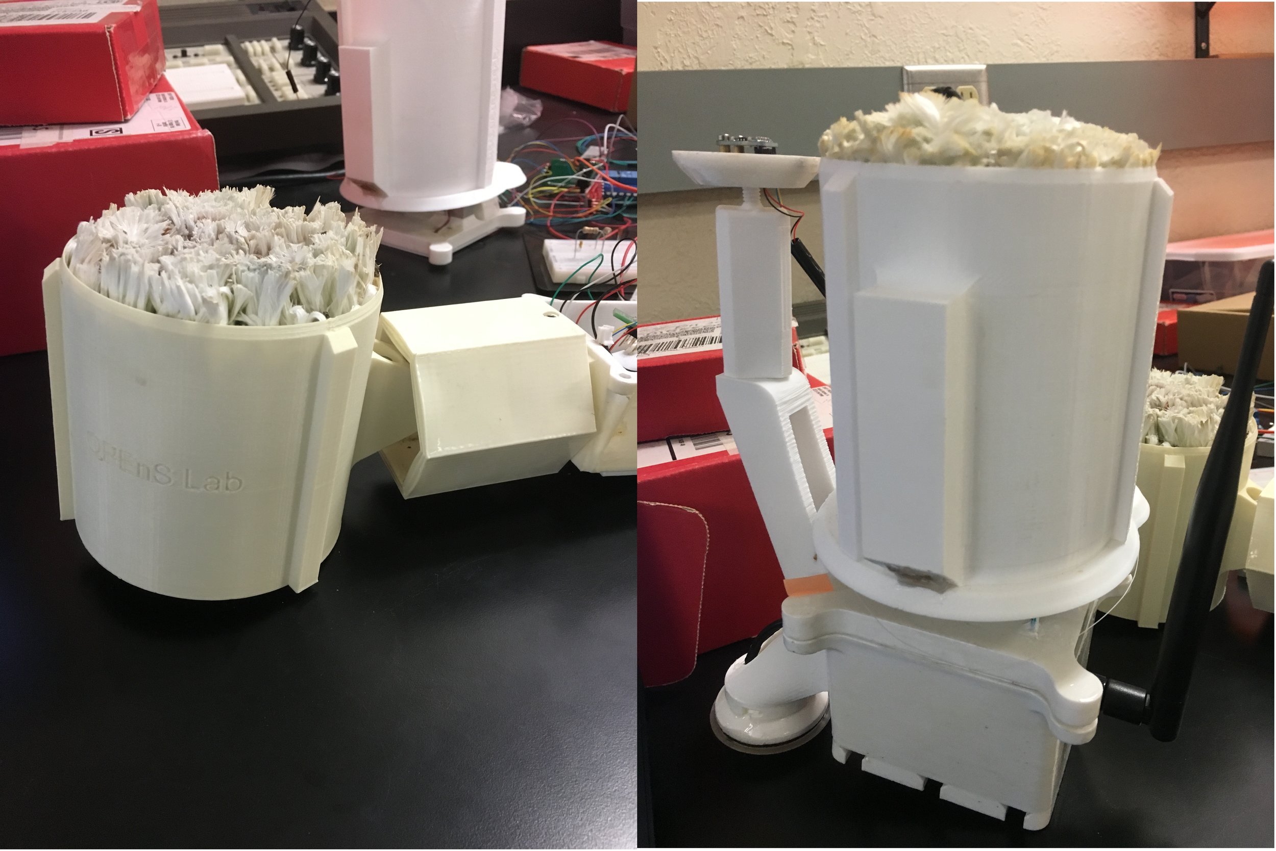
Another improvement we are hoping for this year is sustainability. We are changing the material of the Evaporometer from ABS to ASA filament in order to weatherproof the encasing, making these devices last longer. Depicted below is the encasing after a 3-6-month period vs. newly printed encasing. By using ASA filament, we can reduce the yellowing of the encasing from overexposure of UV radiation.


3-6 Month Used Evaporometer vs. Newly Printed Evaporometer3-6 Month Used Evaporometer vs. Newly Printed Evaporometer

3-6 Month Used Evaporometer vs. Newly Printed Evaporometer

Future of Evaporometer

Dr. Selker is planning on deploying approximately 50 Evaporometers to Africa around May.

A First Configuration of the Freewave Z9-T DEVKIT

Author: Grayland Lunn

Configuring the Freewave Z9-T DEVKIT radio can be at challenging at times, so this is a post meant to supplement the Freewave setup guide. This blog is not intended to cover all of the elements of setting up the radios, but instead to cover some gaps that may exist within the documentation.

The quick start guide can be found at Freewave’s Support Website. Their support website requires registering a free account with your email. A full user guide is also available for the Z9-T DEVKIT and for the Z9-T radio in the ZumLink 900 Series tab of the support website.

It is likely easiest to use the terminal interface tool Tera Term. This is what the quick start guide uses, and it is what the author used to configure the radios. Tera Term can be downloaded here. However, if you are using a unix system, use PuTTY instead to open a USB serial connection to the radios.

Now, let’s get started with setting up the radios. You should have both this blog and the quick start guide open at the same time for best results.

Hardware Setup

  1. Connect the antenna to the radio without any power or other connections.

  2. Ensure the 5 pin x 2 pin jumper on the devkit is connected on the USB side of the pin block and NOT on the TTL (D9 Port) side.

  3. Connect the provided 12V power cable.

  4. Connect the micro USB serial cable between your computer and the Freewave radio. Take note of the COM port that was added, this will be used in the CLI configuration.

Configuring Your Terminal (Windows)

Follow the CLI configuration steps provided in the quick start guide. Be sure to press the S1 interrupt button on the radio every time a new terminal setting configuration is attempted (CLI configuration step 8). If you do not press the S1 interrupt button on the radio before sending enter in the terminal tool, the radio will not connect. Here is an example of the correct setup steps:

  1. Select a new baud rate in the serial port setup pane.

  2. Accept new configuration.

  3. Press the S2 interrupt pin.

  4. Press enter in the terminal window. If the shell does not return a new line with “>” at the line head, the serial port is not configured correctly, go back to step 1 and try another configuration.

The quick start guide steps are for programming the radios out of the box, and the configuration settings may have been changed by another developer, so here are a few common configurations to try if the Freewave CLI is not connecting.

  • Try a different BAUD rate.

    • A baud of 115200 is most common, and 3000000 (three million) is also common and used for uploading new firmware.

    • Available CLI BAUD rates are 9600, 19200, 115200, 230400, 460800, 921600, and 3000000.

  • Try turning flow control off.

    • The two available flow control settings for the radios are Hardware (ACK/NACK for PuTTY) and off.

    • If flow control is turned off, the most likely BAUD rate is 115200. This setting is used with the NavSpark GPS for the Slide Sentinel project.

  • Try a different serial port or plug and unplug the USB connected to the devkit to make sure you are using the right port. Be sure that you are using a micro USB data cable.

  • The data, parity, and stop bits are unlikely to change based on our lab’s current usage, however check the data format of the last use case if you still can’t get the radio to connect to the CLI tool.

Configuring Your Terminal (Mac/Linux)

Unfortunately no TerraTerm port exists for OSX or Linux distributions. If you are using a machine running these operating systems you will need to use an alternative application for establishing terminal serial connections and configuring Freewave Z9-T.

  1. First, plug in the device and determine if your machine recognizes the Freewave Z9-T development kits, open a new terminal and run:

    $ ls /dev/cu.usbserial*
  2. The above command will list all usb serial devices connected to you machine, these devices show up in /dev directory. If a Freewave developer kit is connected and recognized you should see the terminal return something like this:

    $ /dev/cu.usbserial-DEVKIT
  3. The easiest way to establish a serial connection to the device and enter the Freewave shell is using the screen command line tool. Run the below command to verify that you machine has the tool installed.

    $ screen --version 

    If you receive the following error-bash: screen: command not found”, then you must install the tool by installing it:

    $ brew install screen (mac)
    $ sudo apt-get install screen (Linux)
  4. With screen installed, a serial connection can now be created. In a terminal window type the following command:

    $ screen /dev/cu.usbserial-DEVKIT 115200

    Press the interrupt button on the Freewave development kits then enter the screen command. If all goes well your terminal will go blank. Simply hit enter twice and you will be prompted by the Freewave shell. Proceed to “Using the Freewave Shell Command Line Interface” section for configuring the radios properly.

Using the Freewave Shell Command Line Interface

Use of the shell is not covered in depth within the quick start guide, so here are some helpful tips for using the shell.

  • Press tab at any time to auto complete a command or show all available commands.

  • Typing a specific command or group of settings will allow you to see the current value(s) for those settings. Try typing “serialPortConfig” to see the current serial port settings. Make note of these for the next time you need to connect to the radios.

  • Typing “radioSettings” will show the current radio configuration.

  • The shell is not case sensitive, no need to worry about case.

  • To change a value, just type “fakeValue=x” for instance cliBaudRate=115200 will update the baud rate that is used for connecting to the freewave shell.

  • If you want to know all the available values for a setting, type “fakeValue=” and press tab to show all the available values.

  • More description on settings is contained in the Z9-T user reference manual, here.

A Basic Connection Between two DEVKITs (Windows)

The quick start guide provides all the settings necessary for connecting two radios with a wireless link. One setting that could not be changed was the “radioSettings.maxPacketSize” setting. Attempting to change this will always return “RESULT 20: SETTER NOT VALID” however this is not an issue as long as both radios have the same value for maxPacketSize.

Note that you must update the firmware of each radio if it is not up to date. The firmware update guide is in the Z9-T user reference manual, section 8.

When first attempting to connect and send a file via a radio link, follow the data logging steps provided in the quick start guide using this copy of Alice in Wonderland as the test file. It has no <CR> or <LF> characters which cannot be used by the terminal logging software. Once the radios have been configured correctly for the data transfer, start the log on the gateway terminal. And send the file using the Tera Term send option from the terminal connected to the Endpoint.

Be sure that neither terminal is connected to the Freewave shell, this will prevent data transmission.

A successful transmission will show text flowing in both terminals, and the log will be accumulating data. Once transmission is complete, stop logging. Run a file comparison (FC command in windows command prompt) to ensure data was transmitted without error.

A Basic Connection Between two DEVKITs (Mac/Linux)

NOTE: ensure that you have updated the firmware on the radio and “radioSettings.maxPacketSize” is configured to the same value on both radios as detailed in the above section. These configuration steps do not differ between Mac/Linux and Windows.

  1. In order to send a message between the two radios you will need to exit the Freewave shell on both the Gateway and Endpoint. From the Freewave shell connections type:

    exit 

    Hit enter. Then press the reset button on the dev kit boards.

  2. Download the copy of Alice in Wonderland, and ensure you know the full path to the file.

  3. Now from the terminal which previously held a connection with the Freewave Z9-T configured as a Gateway enter:

    Ctrl + a

    Then enter a colon like so,

    :
  4. The above sequence of keystrokes signals the screen tool that you are going to enter a command. In order to send the file we need to first load the copy of Alice in Wonderland into a buffer. To do this run:

    readreg p /path/to/Alice/In/Wonderland

    The terminal should return the following statement:

    Slurped X character into buffer
  5. Now we are ready to send the file. I recommend having the terminal window connected to the Freewave Endpoint in visible sight so you can see the file contents printed to stdout as the Endpoint receives the file. To send the file to the Gateway type the input command signal Ctrl + a and : (colon) then enter:

    paste p
  6. You should see a steady stream of data printed to the terminal window connected to the Endpoint Freewave. Congratulations you just transferred Lewis Carrol’s Alice in Wonderland across the air between two Freewave Z9-T’s!

Cosmic Ray Environmental Sensing Online

Author: Emre Akbulut

We are in the preliminary stages of analyzing different options for how to modify the Cosmic Watch v2’s configuration and code to suit our purposes in detecting gamma rays. There are some assumption based methods like using the Cosmic Watch’s master-slave configuration and deducting the difference between them as the total amount of gamma rays. However, by working with the radiation detection group we are hoping to find ways to employ more exact methods in gamma ray detection.

While waiting for parts I began reading about scintillators and SiPMs being used to detect gamma rays and muons. Muons are have an average energy level of 4 GeV at sea level [1] while gamma rays have a much lower energy range typically defined as 100 KeV to 5 MeV [2]. The way the Cosmic Watch Muon detector works is when a muon hits the scintillator it emits light, the SiPM then sees this emission of light and converts it to a voltage pulse. The resulting pulse ranges from 10-100mV, which is too small to be read by the Arduino Nano, so the signal is amplified by 20-25 through an op-amp so it can be read by the Nano as an ADC voltage value.

One interesting thing I found was how one individual created a DIY gamma ray detector with a miniature solar cell [3]. This functioned similar to the Cosmic Watch in how a pulse was created from gamma rays and then amplified to be displayed. It may be worth looking into if this method of detection could be improved to suit our purposes.

Another thing I noticed when looking through the materials we are using for the Muon detector we have is that the scintillator we have, bc408, is not meant for gamma ray detection. However, the bc412 from the same manufacturer can detect gamma rays from 100 KeV to 5 MeV [4]. We will need to meet with the radiation detection group at OSU first before considering the use of bc412 material.

[1] “Muons.” [Online]. Available: https://cosmic.lbl.gov/SKliewer/Cosmic_Rays/Muons.htm. [Accessed: 24-Jan-2019].

[2] “Radioactivity : Gamma Rays in Matter.” [Online]. Available: http://www.radioactivity.eu.com/site/pages/Gamma_Matter.htm. [Accessed: 24-Jan-2019].

[3] “Alan Yates’ Laboratory – Photodiode Gamma Ray Detector.” [Online]. Available: http://www.vk2zay.net/article/265. [Accessed: 24-Jan-2019].

[4] “BC-408, BC-412, BC-416 | Products | Saint-Gobain Crystals.” [Online]. Available: https://www.crystals.saint-gobain.com/products/bc-408-bc-412-bc-416. [Accessed: 24-Jan-2019].

March 29, 2019

Major developments have happened since the last blog post. Some questions that were answered from the previous post:

  • BC412 and plastic scintillators will not offer the resolution we need for detecting gamma rays due to their low Z value. This is because the method of using gamma ray detection to get the snow water equivalency (SWE) of snow requires very high resolution detection.
  • Steven Czyz, one of Dr. Farsoni’s Ph.D students informed me and Selker on the issues with an inexpensive way to detect gamma rays mentioned in the above bullet point. However, Steven’s ph.D thesis project is a full spectrum, small gamma ray detector which cost about $5,000 to build two. He said that after he finishes his ph.D project thesis that his gamma ray detectors will probably be not used; so it is possible we could use them.

Originally with our backgrounds we were expecting gamma ray detection would be inexpensive and neutron detection would require very expensive that would only emit light due to neutrons.

On March 15th, 2019 during a meeting with John we were reaching out to Eljen Technology inquiring about their neutron detectors. John explained the overview of the CRES project and asked about their green sandwich “paddle” for thermal neutrons and asked if it was possible to get any defective scintillators to help orient ourselves with neutron detection.

About two weeks later they decided to contribute an entire 6 cm by 20 cm green sandwich “paddle”, which is composed of two scintillating tiles, EJ-426, and a green wavelength shiftier EJ-280. They sourced this from a larger order in Europe and there is already a small square cut on one of the tiles to for using a SiPM with the sandwich. This contribution is worth about $200, about the same price it took to assemble the muon detector.

To my excitement about this I started looking into this green paddle configuration to see what modifications we would need to make to the current CRES electronics. First off was understanding if our SiPM for blue light would work. The color wavelength chart below for reference will help understand why the sandwich configuration is used.


Color Wavelength Chart. Fig. 1.Color Wavelength Chart. Fig. 1.

Color Wavelength Chart. Fig. 1.

EJ-426’s emission spectrum peaks around 450 nm which is on the boarder of violet and blue light. The EJ-280 takes the violet/blue light and then shifts the wavelength to green light. This sandwich has some advantages over typical light collection methods like used in the Cosmic Watch V2 Muon Detector.

The OPEnS Power Control Board: A circuit to reduce the standby current draw of microcontroller projects to 130uA

At the OPEnS Lab, we’ve found a common requirement amongst our projects: a long, long, long battery life. The OPEnSampler was particularly challenging due to its simultaneous 3.3V, 5V, and 12V power requirements. MOSFET circuits exist that can manipulate power sources and drop their standby currents to near-zero, but designing these in a way that latched their state in both directions, and were powered exclusively from the source battery, was difficult. This short blog post will discuss the features and considerations of Release 1.0.0 of the OPEnS Power Control Board.


RL_board.jpgRL_board.jpg

The schematic


Power7.1.pngPower7.1.png

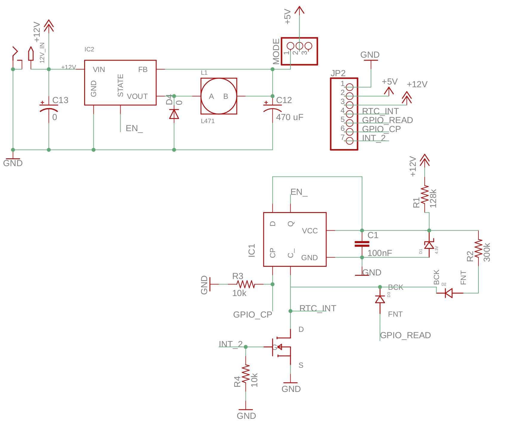
The circuit was designed by Mitch Nelke. There are two core integrated circuits in this board. IC1 represents the flip flop IC and is responsible for latching its EN-bar output HIGH or LOW after a HIGH pulse on its Clock Pulse input or a LOW pulse on its C-bar input, respectively. IC2 represents the 12v-5v switching regulator component that drops the battery’s 12v supply to the 5v used to power the microcontroller and other components.


The Flip Flop

The flip flop circuit power is sourced from the battery’s raw 12v, though it is dropped down to 4.3v by the zener diode D1. R1 was chosen based on a minimum required current of 60uA, derived from the max required input current of the switching regulator’s enable pin and the current required by the flip flop IC plus a bit of extra as a buffer. This 4.3v source is also used to pull the flip flop’s D input HIGH at all times. The Clock Pulse (CP) input is pulled to ground by a 10k resistor. On a rising edge on CP, the flip flop reads the boolean state of D and sets its Q output to match that value. With this setup, a HIGH pulse to CP will always set Q HIGH.


The C-bar input has a weak pullup resistor, R2, to 4.3v. When C-bar is pulled LOW, such as through the RTC_INT input or a HIGH input from INT_2, the flip flop IC ignores any clock pulses and sets its Q output LOW. When C-bar is raised HIGH, Q will stay LOW until the next clock pulse.


GPIO_READ allows a microcontroller input pin to read the state of the real time clock’s (RTC) interrupt alarm while the device is on. RTC_INT should be attached directly to the RTC’s INT/SQW pin, and GPIO_CP should be attached to the microcontroller’s output pin that is responsible for shutting the device off.


The Switching Regulator

The switching regulator efficiently converts the 12v input to a 5v output. This part of the circuit is essentially ripped from the LM2575 datasheet’s recommended circuit. Its EN-bar input acts as a low-true output-enable and is attached directly to the flip flop’s Q output. The 5v output of the regulator is fed through the MODE jumper. The MODE jumper’s first two pins should be connected during regular use, but should be disconnected when a USB is plugged into the microcontroller (to program it, for example) to not have competing 5v supplies.


The Board

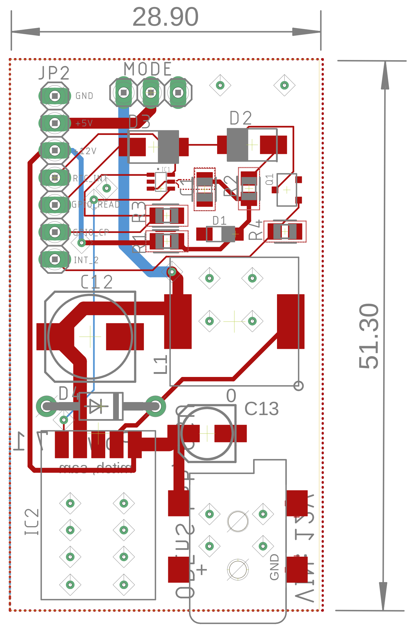
The board layout was done in EAGLE CAD by Sam Edwards. I’ve added dimensions and turned off tStop and pour planes so it is more clear.


Power7.1-board.pngPower7.1-board.png

Connections

The board is designed specifically to work with Adafruit’s Feather M0 microcontroller series. It should be powered by a 12v battery plugged into the 2.5×5.5mm barrel jack receptacle.

  • The +5V pin should connect to the M0’s USB power pin or the Arduino Uno’s Vin. MODE should be closed with a jumper to enable the 5v output of the board.

  • The +12V output should be connected to any circuitry that requires 12v.

  • RTC_INT should be connected to the real time clock’s interrupt output, or any other independent circuitry that sends a LOW-TRUE signal to turn the device on.

  • GPIO_READ should be connected to an input pin on the microcontroller if the real time clock’s alarm needs to be read by the microcontroller when power is already enabled.

  • GPIO_CP should be connected to the microcontroller’s digital output that is designated as the shutoff pin.

  • INT2 should be connected to any external circuitry that should power the device on with a HIGH-TRUE signal.


Testing

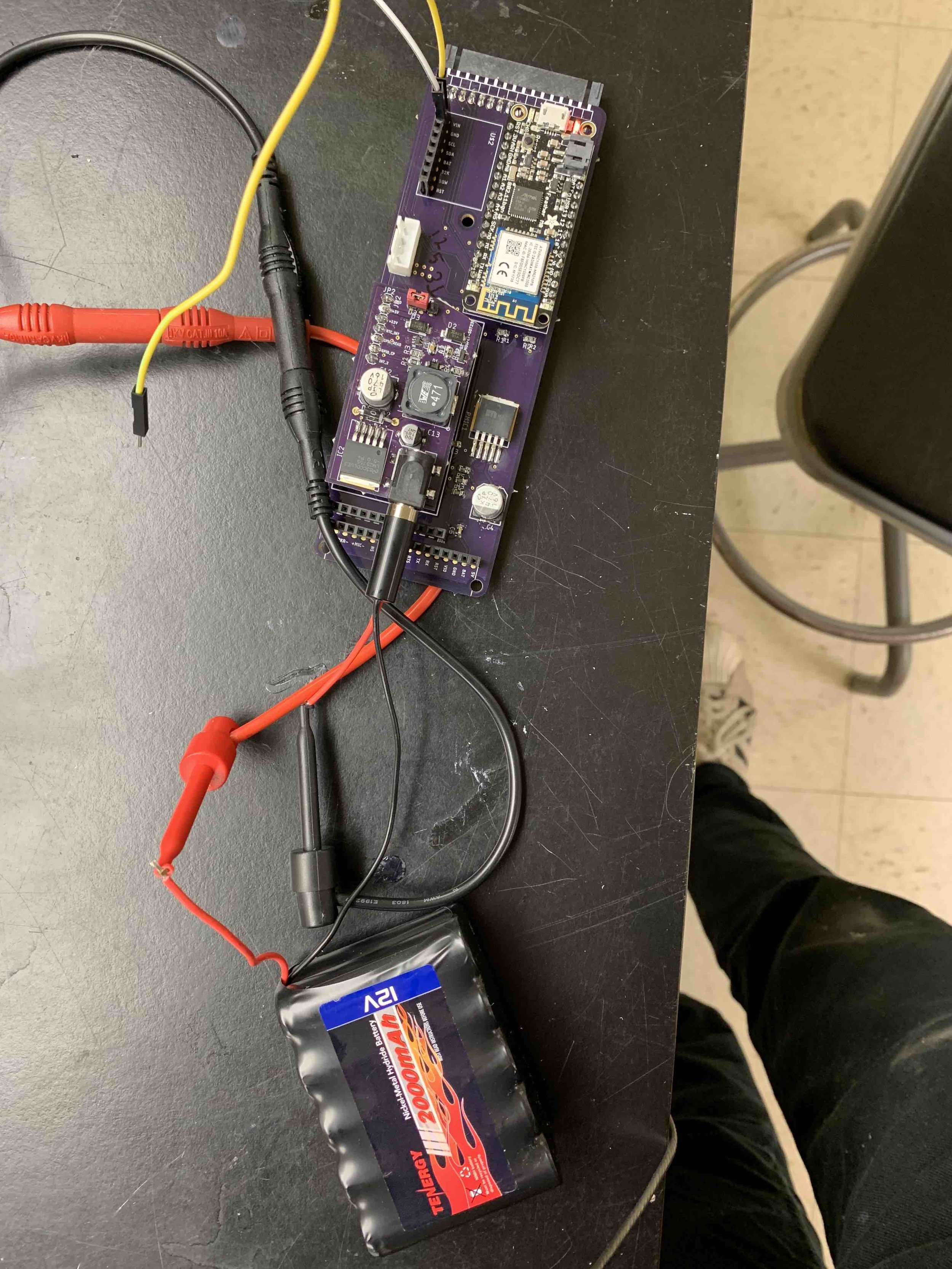
A current draw test was conducted by measuring the current with a multimeter between the battery’s positive lead and the positive input on the power control board. The power control board was attached to the OPEnSampler’s Microcontroller Breakout Board, upon which Adafruit’s Feather M0 Wifi microcontroller was also attached. The microcontroller was programmed ahead of time to simply power its LED upon powering up. One jumper cable was connected to the real time clock’s 3v3 power pin, supplied by the M0, and was temporarily connected to the power control board’s GPIO_CP pin to turn the device off. Another jumper cable was connected to ground and RTC_INT to turn the device on.


Testing.jpgTesting.jpg


The device had a current draw of 22mA when powered on and only 130uA when powered off. When powered by the small 2000mAH, 12v battery used on the OPEnSampler, the device will have a maximum standby battery life of 641 days (not accounting for the battery’s internal leakage current). If the device had used normal sleep methods that can reduce the consumption down to 1.5mA, the maximum standby life would have only been 55 days. With no standby mode at all, the battery life would have been less than four days.


Considerations

An important consideration is that I am not an electrical engineer, nor am I pursuing a degree in electrical engineering. There is much to be improved on this board, and if you have any ideas, or find a bug in its design, you shouldn’t hesitate to contact the OPEnS Lab or leave a comment on this post! Additionally, this was only tested on Adafruit’s Feather M0 Wifi breakout, so your mileage may vary on other boards (especially ones that are not in the Feather M0 family!).


Finally, when using this board it is important to understand that the microcontroller is completely shut down on “standby” mode. This means that after the real time clock wakes the device up, it will start at the setup routine and any variables stored in flash will be erased. Be sure to use non-volatile storage methods for variables that must be saved between power cycles. The OPEnS Power board, for example, includes a small EEPROM chip. Adafruit’s Feather M0 Express includes extra SPI or QSPI flash memory that isn’t erased between power cycles as well.


Conclusion

The primary application of the OPEnS Power Control Board is to increase the battery life of a sensor suite powered by a 12v, 2000mAH battery. This board is capable of dropping the standby current of microcontroller-based projects down to 130 micro-amps. The minimum standby current that could be achieved previously was about 1.5mA based on Adafruit’s tutorial linked previously. The OPEnS Power Control Board increased the theoretical max standby battery life from 55 days to 641 days. The device fully shuts off on standby and wakes up from pulses to either of its two interrupt vectors, one HIGH-TRUE and one LOW-TRUE.

Link to GitHub

DOI

Written by Mitch Nelke, OPEnS Lab OSU