RFID Sensor Update 2

Author: Brett Stoddard

Hi everyone, this week has been an exciting one for the world of OPEnS RFID moisture sensing. Since the update, we have found ways to make the sensors even more reliable and sensitive. Two updates have allowed for this development.

The first major modification came when “tails” were added to the RFID tag. These tails are made out of a paperlike material that’s designed to suck up and hold and moisture it comes into contact with. The more moisture it touches, the more water it sucks up thanks to capillary action. Tails can be positioned on the sensor to hold the liquid in the most moisture sensitive area of the tag to maximize the accuracy of readings. Sure enough, as soon as we started gathering data with the tails attached the reliability of our measurements improved by a lot. An image from one of Smart Trac’s technical documents showcases the tail below. All future testing will be done using these tags.


Image of a tail attached to an RFID tag


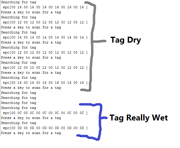
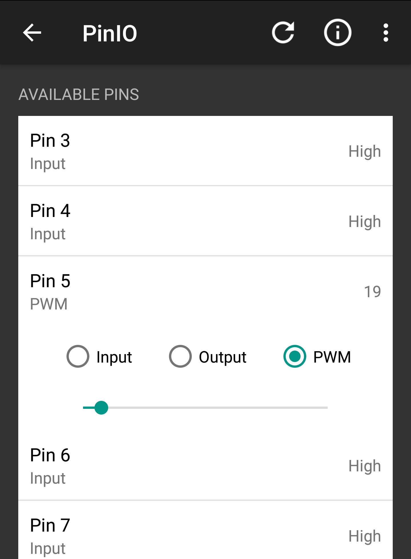
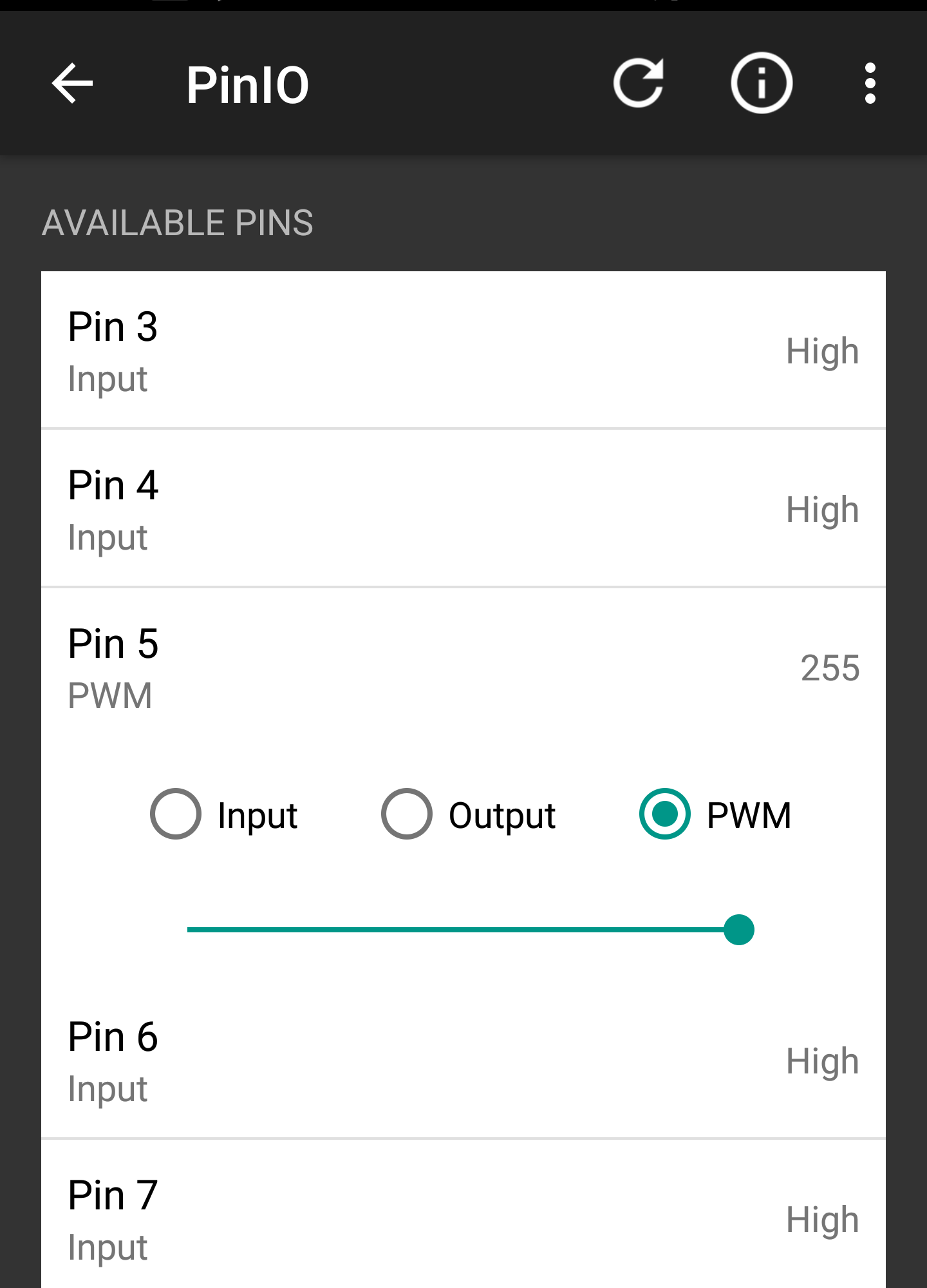
The second change was implemented on the software side of things. Before this week the sensor value was only read once and then outputted. The new code took 100 readings and then outputted the mean value. By using this method, more reliable and accurate readings were made. These new readings improved consistency across all of the tags for sensing extremely wet, extremely dry, and moist tail conditions. In the future, we will examine the exact distribution of the readings to determine the minimum number of readings that are needed to get a value with 80-90% certainty. The example code can be seen in this folder of the RFID library. This code is not yet optimized.

3D Printed Hyperspectral Camera Mount

I have 3D printed the pieces from the initial design. Here are pictures of the pieces: 


Shaft CouplerShaft Coupler

Shaft Coupler


Assembled Shaft CouplerAssembled Shaft Coupler

Assembled Shaft Coupler

This is one of the most important pieces of the whole assembly. This made from two pieces that screw together. The top piece holds the 360 swivel in place and the bottom piece is the shaft coupler. The next iteration needs some improvements, but this design works great. 


Shaft BaseShaft Base

Shaft Base

This base is the rest for the shaft coupler; the base plate of the shaft coupler rests on the bearings. The shaft base connects to the motor housing making a solid base for the camera. 


Disassembled baseDisassembled base

Disassembled base


Assembled Base Assembled Base 

Assembled Base 

Here is the assembled piece. The motor electronics have been tested and soon will be integrated. Some more things have to be edited in the desing before printing a working version. 

The post before this one outlines the CAD for these pieces, for a more detailed description of the design look below. 

What’s Up with the LoRa Devices

Abstract:

This post describes all progress up to this point and the integration of LoRa communication into the currently in progress Evaporometer project.

Our Progress:

In the past few weeks, I’ve been working with another student named Manuel to apply the LoRa devices to a rain catchment device designed to measure evaporation.  Below is a picture of the strain gauge rain catchment system he built for the project.  The LoRa device can be placed on the platform where a load cell can be hooked up to our LoRa system to measure and transmit data to our LoRa receiver and to an offsite server.  


Since the LoRa device will need to transfer data as precisely as our load cell can measure, the code will need to be adjusted to accommodate integer and float values with adjustable decimal precision.  I have made the proper updates to the code and will post more details on that in the future.

What’s Next:

We are moving quickly towards field testing these LoRa devices with the Evaporometer but there are a few changes that still need to be made.  The LoRa transmitters, which will be out in the field, will need a weatherproof housing and a portable power source.  Also our current transmission frequency is not suitable for a lot of ongoing communication, so our LoRa breakouts will also need to be replaced new ones that can transmit at a higher 915 mHz frequency.   

Marissa Kwon Undergraduate Student Researcher

RFID Sensor Update

Author: Brett Stoddard

Hello all, it’s been a while since the last sensor status but from now on I’ll be working to increase my posting frequency.

Since the last update, many things have been happening on the sensor end. First, the OPEnS lab bought a new RFID module to interface with the Arduino UNO and have semi-officially scrapped the LinkSprite LSID-0702 reader. From here on out, we will be using the SparkFun Simultaneous RFID Reader – M6E Nano shield. I was really excited to get working with this reader because it’s documentation is a lot more readable and through than the other modules I’ve worked with.

That documentation included a SparkFun proprietary library especially made for use with the Arduino UNO. I forked this library on GitHub and have been adding to it a few functions specifically geared towards reading the moisture information from Smart Trac RFID tags. For the most part, these functions seem to work! The original SparkFun library is available by clicking here. The OPEnS lab version of it that I have and will be adding to can be found by clicking here.

The rest of this blog post will be dedicated to the results of tests run to prove that the retrieved values are dependent on the actual moisture of the chips. “Wet” tags were held under a stream of moving water in the sink for five to ten seconds. “Dry” tags are either tags that were never wet or ones that were set out to dry for a few days. 

FIGURE 1. Raw, unprepared data from the serial port of the Arduino UNO when example code from the library is run.

This data was gathered by modifying a read EPC byte command to read a different registry. What that means is that the data is unparced and looks gross. The important thing from this data is that the sensor code was reading a different number when it was wetted. When dry the tag had a value of either 12 or 14 HEX (18 or 20 decimal). Then when that same tag was run under the sink it read a value of 0C or 0C HEX (12 or 13 decimal). Being able to tell the difference between really wet and completely dry is a large step forward for this project and this data, if consistent, will allow us to do just that. However, as always, more testing will be needed to make this process robust enough for use in the field. 

Coding with the nRF08001 Chip and Other Evils

Testing Aftermath

After concluding testing on basic functionality earlier this week with positive results , it was time to dig into the real work… developing a protocol that would allow this Bluetooth LE breakout board to be used to transmit sensor data in a convenient and uniform way across the “Internet Of Agriculture” project . In addition, a second nRF08001 module was set up, and experimenting with two modules began.

Phase one – understanding the “out of the box” software

Before trying to construct an entire comprehensive script from scratch,  I thought it would be worth my time to familiarize myself with what others have done in some of the demo codes I explored here on Github.  

The code currently running on the two Arduinos (found here) has be modified slightly by myself but in general the  framework is done using universal asynchronous receiver/transmitter (UART)  protocol , where the data format and transmission speeds are configurable. The electric signaling levels and methods (such as differential signaling, etc.) are handled by a driver circuit external to the UART, in our case an Ardiuno uno, and eventually something as small as an Adafruit Pro Trinket . In other words, the UART takes one channel to transmit data and one to receive it.  

UART Sketch in detail (Part 1)

Initialization

Like most Arduino sketches the first step is to initialize the device in question (in our case the Arduino or Pro Trinket), and prepare the hardware for the data its about to send and receive. You’ll need to include the header files and define the pins used. Since we’re using hardware SPI, the CLK/MOSI and MISO pins are fixed (see wiring scheme in “Getting Started with the nFR08001” blog). 

the RDY pin is the only pin that must be an interrupt pin. We’ll use 2, most Arduino’s can use 2 or 3.

Then create the Adafruit_BLE_UART object at the top as shown below. 


These few lines of code are enough to get the Arduino oriented to the hardware and are the first steps to begin further use of the BLE module.

Unfortunately due to time constraints and hardware not cooperating, this is as far as we got this week. However, further exploration will continue.    

– Tom DeBell, Beginning Researcher Support Program researcher

Reversing The Motor Direction To Drain A Sample

I’ve attached a video of the nearly finished water sampler’s ability to drain a sample without disconnecting the bag from the system. The current system is not proven to be air-tight and should not be expected to be so, but this will help to reduce error and eliminate the need to disassemble the tubing. Instead, the user can specify which bag to sample and run the pumps in reverse through serial commands through a computer console.

ESP 8266 and IFTTT

By: Alex Grejuc

Background:

I have been working on connecting to IFTTT using the ESP. IFTTT is a platform that makes it easy to connect different web apps and services to create applets or recipes. They work in an If this, then that (that is where the letters IFTTT come from) format. For example, if I like a video on YouTube, save its name and link to a list on Evernote.

IFTTT has a service called Maker that allows a user to send a web request to their Maker service which can then trigger an action. I used this feature to create an applet, which, when triggered by the ESP will send data to a Google Drive spreadsheet.

Process:

This will be wired the same way as all my previous Arduino and ESP guides. Most of the code is fairly similar and it is explained there as well. The wiring is here and the general info about sending GET requests is here.

The first step is to create an IFTTT account and then create an applet (this link answers many of the questions about applets) using Maker.

After creating an applet, go into settings on the Maker page.


settingssettings

Then, copy your personal URL and go to that page.


On this page, you can see the information for sending HTTP requests and the full link that can be used in a GET request. The code will show how to add data values which can be sent over as query parameters in the request.


Once this is all set up, you have the necessary information to send data to the web using IFTTT and your ESP.

Next, download the code, add your credentials, and then upload it to the Arduino.

This guide may be helpful, it is how I got my start. However, like many of the guides, this uses the ESPWifi library which I did not use.

Hyperspectral Camera Pole Mount

This project is intended to be a mount for a hyperspectral camera. The interesting thing about this project is that the mount has to be able rotate and tilt up and down. The spinning and tilting will be determined by the user of the camera. Here I will post pictures of the CAD renderings and explain how they all go together. 


CAD model of pole mountCAD model of pole mount

CAD model of pole mount

This first image is the model of the first design. This mount is composed of four printed pieces: motor mount, shaft rest, and the shaft( motor coupler). the shaft is made out of two printed pieces that are then screwed together.

This 3D model is the shaft base/rest. The base has four ball bearings on which the shaft will be resting on. Theses ball bearings will allow for a smooth rotation of the camera. If these were not to be there, the shaft would be resting on plastic and the would potentially have a rough rotation. The hexagons that extrude from the sides are the locations of the ball bearings. This base will be the connecting piece between the shaft and motor mount. 

This 3D model is the motor housing. It is a pretty straightforward design. This model will house the motor and connect to the base that will be connected to the pole. It has slots that will allow airflow through the piece and keep the motor from overheating. 

These two models are the shaft/ motor coupler. The top model is the piece that attaches to the 360 swivel and the bottom model screws on. This is the piece that rests on the four ball bearings and will be spinning.

I will now be printing the pieces and verifying that they all fit how they should be. Most of this design will be used for the other project. This other project will also be for the hyperspectral camera, but this design will have rails instead of a pole. 

Asynchronously Reading a Sonar Distance Sensor

Author: Jonah Siekmann

To get the quadcopter to fly at a set altitude above crops, we need to use a distance sensor (or more likely, a combination of distance sensors). We’re going to use a sonar distance sensor for at least part of the altitude calculation. However, the speed of sound is pretty slow. In the time it takes the sensor to send a ping and receive the echo, dozens of milliseconds could have passed. So we need to read it asynchronously. This turned out to be a little trickier than I first thought, so I made an instructable on it. You can read it here:

https://www.instructables.com/id/Asynchronously-Reading-the-HC-SR04-Sensor/

More Testing with the nRF08001 Bluetooth LE

Note: The nRF8001 sends out packets of data, 20 bytes at time. Keep this in mind if you want to send a lot of data it will be packetized into chunks of 20. You can of course send less than 20 bytes.

Exploring Mobile Interface

After initial setup and software tests, I was able to explore the Adafruit developer smart phone application found in the android market, “BlueFruit LE”. (APK file linked here

Much like Serial you can use the .write and .print functions allow us to send data out to the connected device:

Features included in Bluefruit LE App


Home screen of the "Bluefruit LE" smartphone applicationHome screen of the "Bluefruit LE" smartphone application

Home screen of the “Bluefruit LE” smartphone application


Display after connection with Bluetooth moduleDisplay after connection with Bluetooth module

Display after connection with Bluetooth module

Info

Displays MAC address and other relevant Device Information


Screenshot_20170412-101741.pngScreenshot_20170412-101741.png


UART


Screenshot showing a message being transmitted to the Arduino from my smartphone Screenshot showing a message being transmitted to the Arduino from my smartphone 

Screenshot showing a message being transmitted to the Arduino from my smartphone 

The “UART” function allows a basic text message interface from smartphone to the Arduino Series monitor. However, after testing it was apparent that although the application allows infinite characters of transmission, the messages are broken apart into 20 character fragments due to the data transmitting capabilities of the bluetooth chip.


Snip showing successful reception of the message from my smartphone to the Arduino seriel monitorSnip showing successful reception of the message from my smartphone to the Arduino seriel monitor

Snip showing successful reception of the message from my smartphone to the Arduino seriel monitor


Pin I/O

The Pin I/O section of the mobile phone application allows the user to control input and output of pins (both analog and digital) on Arduino shield. However, this particular function required significant code modification in order to allow functionality on Android enabled devices. Once the code is finalized it will be published and linked here. In order to display this faciniating functionality a small demo was contructed in order to deminstate the smart phone interfaces capabilities. 


With just a slide of my finger I am able to modify the signal strength being admitted from the Arduino With just a slide of my finger I am able to modify the signal strength being admitted from the Arduino 

With just a slide of my finger I am able to modify the signal strength being admitted from the Arduino 


The Blue LED is only lightly illuminated due to low PWM signal as specified by the photo on the left The Blue LED is only lightly illuminated due to low PWM signal as specified by the photo on the left 

The Blue LED is only lightly illuminated due to low PWM signal as specified by the photo on the left 


The PWM slider was moved all the way to right to allow for maximum signal strengthThe PWM slider was moved all the way to right to allow for maximum signal strength

The PWM slider was moved all the way to right to allow for maximum signal strength


The increased signal strength as shown on the left caused the LED to shine brightlyThe increased signal strength as shown on the left caused the LED to shine brightly

The increased signal strength as shown on the left caused the LED to shine brightly

This section of the Bluefruit LE application appears to be very useful, unstable and will require further explanation.

Controller

Streams sensor data from smart phone sensors (Quaternion (6-axis accelerometer), Accelerometer, Gyro, Magnetometer, Location)

Beacon

Puts smartphone in a state to receive pop-up text messages from serial monitor up to 20 characters  


Snip from the Arduino Serial Monitor during transmission testingSnip from the Arduino Serial Monitor during transmission testing

Snip from the Arduino Serial Monitor during transmission testing


Screenshot of the recived message from the Ardiuno Screenshot of the recived message from the Ardiuno 

Screenshot of the recived message from the Ardiuno 


          Messages are restricted to only 20 characters           Messages are restricted to only 20 characters 

          Messages are restricted to only 20 characters 

Neopixel

Needs further exploration.


Conclusions

**Initial testing of connectivity shows an approximate range of 20 feet for reliable signal strength.**

After initial testing it would appear that  the Pin I/O will have the most practical capabilities and research of its functionality will continue. 


– Tom DeBell, Beginning Researcher Support Program researcher