Author: Tom DeBell
Update 10/3/18
The description of process of using PushingBox and the Google scripts was updated 10/3/18 (primarily with regards to the usage and interfacing with the Google Script). The most up to date and comprehensive tutorial is now maintained here.
Abstract
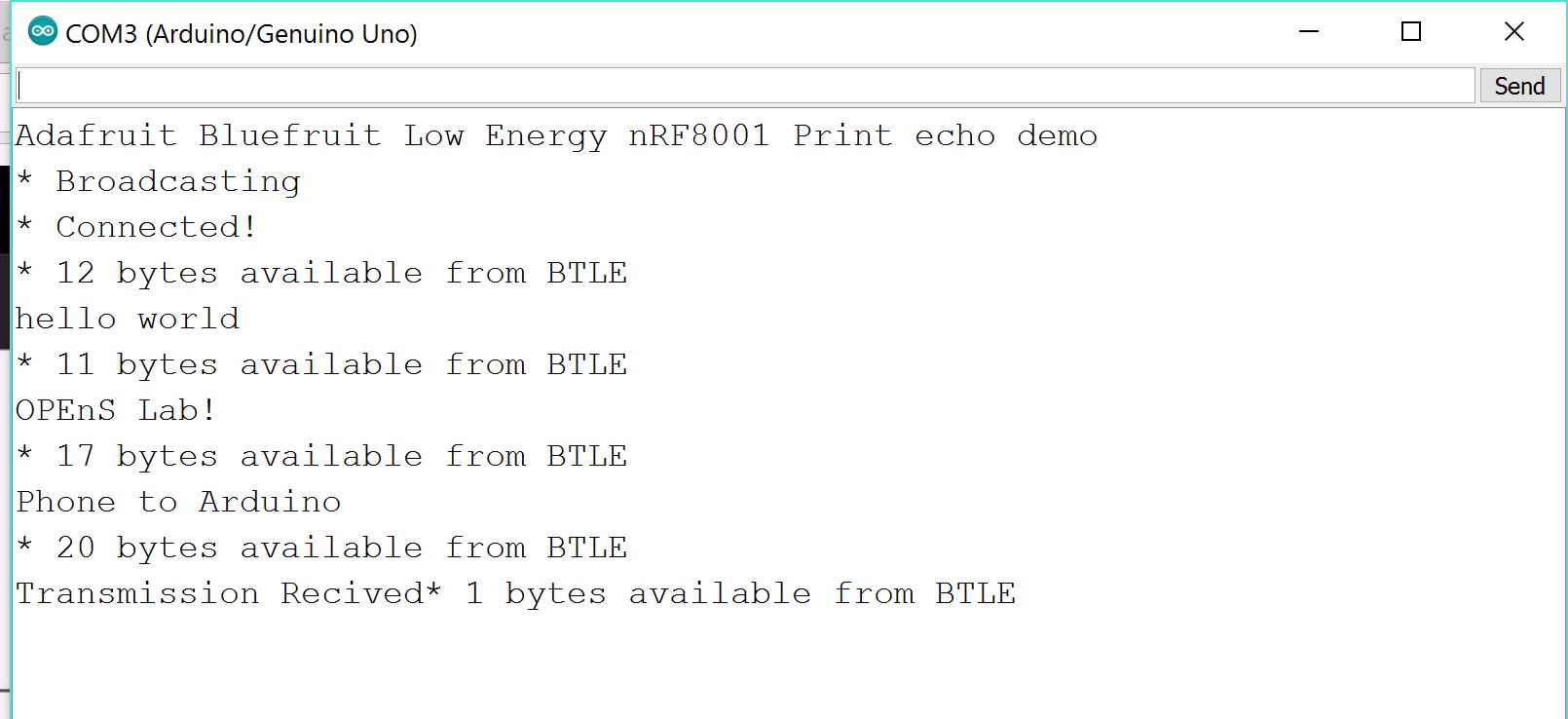
Connecting… Connecting… Transmission Received!
After months of prototyping, experimenting and redesigning we have successfully deployed our first, “fully open source” transmitter and receiver with near real time updates to a google spreadsheet. This post will give a step by step procedure on how to set up all the software and web interfaces for this project.
Step One – Creating and Deploying your Google Sheet
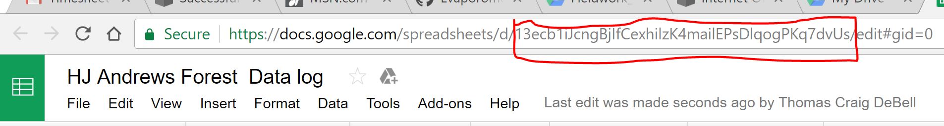
A) Log in to your free Google account and create a new “Google Sheet,” this is the spreadsheet which will be populated by the sensor data received by the Ethernet Featherwing data logger. At this point, you will need to copy and save your spreadsheets URL key for use in your Arduino code. This key is listed in the URL between the “/d/ ” and the “/edit ” of your new spreadsheet (see red box).
B) Name your Spreadsheet something original like “Environmental Data,” now we must create our Google App Script (similar to JavaScript) which will process our data and populate our spreadsheet correctly. To insert our Google App Script we first navigate from our spreadsheet to the Script Editor, found under the Tools tab:
Tools →Script Editor
We will now be on the Google Script Editor page. Now we can name our Gscript something extra-creative like “My Environmental GScript”, but do not have to. Fortunately, we do not have much that we have to do on the Script editor page.
1) Copy and Paste the Google Script code into the Editor. (link to GitHub with all needed codes here)
2) Save the script: File→Save All
3) Deploy as a web App: Publish-→ Deploy as web App…
C) Our final Step for setting up our Google sheet will involve configuring the Web deployment parameters. It is important you set all these fields correctly. If you don’t set all four fields exactly your spreadsheet won’t work properly (trust me…). This step takes place immedietly after clicking “Deploy as Web App”.
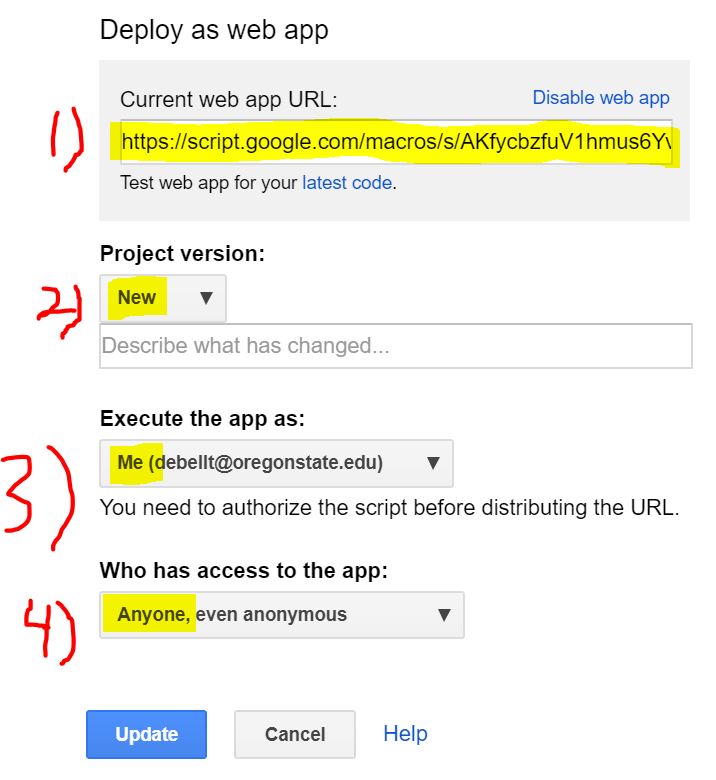
Field 1) Copy and Save the “Current web app URL:“ which has just been generated, we will need this later when we configure our API in PushingBox.
Field 2) Save a project version as “new” on each iteration, it’s important to note that if you don’t make a new project version for each script revision you make (if you decide to make any revisions), your script revisions won’t be updated on the web. This is counter-intuitive, and easy to neglect, but this is currently how Google has this system configured.
Field 3) “Execute the app as: “ set this to “me(your GMail here) ”.
Field 4) “Who has access to the app: “ set this to “anyone, even anonymous.” *This is important, and allows Pushingbox access the spreadsheet.*
Step Two – PushingBox API
Pushingbox.com serves as simple, free, and easy Application Programming Interface (API) middleman in allowing our Evaporometer data to be palatable to Google Sheets. The need for using the PushingBox API intermediary is to turn our HTTP Ethernet transmitted data into Google compliant HTTPS encrypted data. Although other programmers have found workarounds to this system (found here) using PushingBox is easier, and we are given up to 1,000 requests (Data Transmissions) a day.
*1,000 push requests is more than enough for updates every 2 minutes in a 24-hour cycle but not enough for minute by minute updates (thus the “” around real time) but this service is completely free.*
Below are the steps for configuring Pushingbox to work with our data:
1. Create a PushingBox account using your Gmail.
2. At the top click on “My Services”
3. While now in “My Services” go to the “Add a service” box and click on “Add a service”.
4. The service you will want to create is the last item on the list of services and is called: ”CustomURL, Set your own service !”. Now select this CustomUrl service.
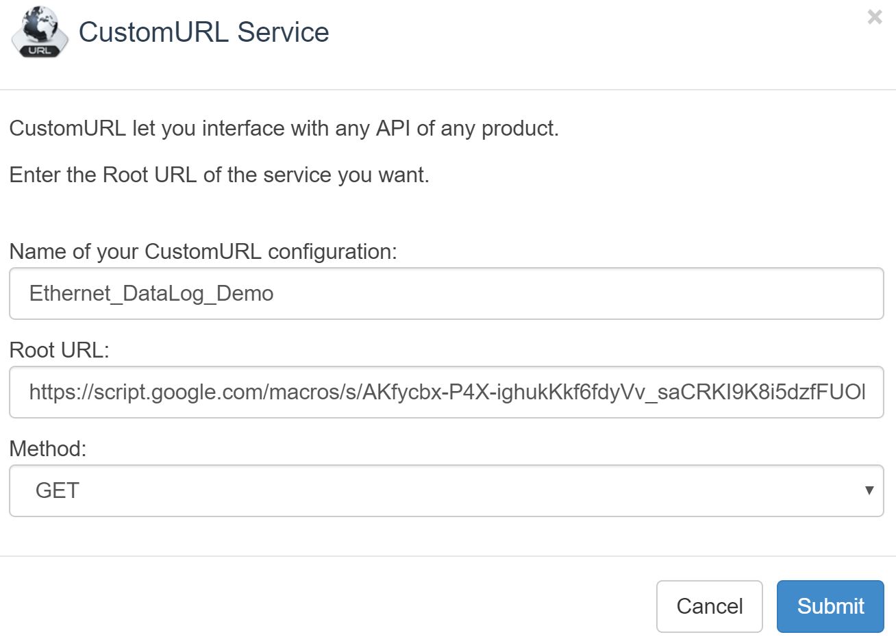
5. A box will open up and ask for three items. Fill them out as below, then hit submit
Name of your CustomURL configuration:
Root URL: This url will start with https://script.google.com… as this is your Google Script address saved from Part 1
6. After submitting your service you must now create a scenario for the service. To do this select “My Scenarios” at the top of the page.
7. Enter an appropriate name for your scenario in the “Create a scenario or add a device” box. After you name your service click the “add” button to the right.
8. Now it will ask to “Add an action for your scenario” You should now choose the “Add an action to this service” button listed next to the service name you created in the previous step. This assigns your new scenario to your new service.
9. A data box will open asking you for your “Get” or “Post” method (we use the Get method although this seems counter-intuitive). For recording all our Evaporometer data into your Google sheet you need to link your variable names listed in your Google App Script to the names listed in our Arduino sketch. Formatting the names correctly in the Pushingbox API will accomplish this linking task.
Copy and paste the following string into your box.
?key0=$key0amp;val0=$val0amp;key1=$key1amp;val1=$val1amp;key2=$key2amp;val2=$val2amp;key3=$key3amp;val3=$val3amp;key4=$key4amp;val4=$val4amp;key5=$key5amp;val5=$val5amp;key6=$key6amp;val6=$val6amp;key7=$key7amp;val7=$val7amp;key8=$key8amp;val8=$val8amp;key9=$key9amp;val9=$val9amp;key10=$key10amp;val10=$val10amp;key11=$key11amp;val11=$val11amp;key12=$key12amp;val12=$val12amp;key13=$key13amp;val13=$val13amp;key14=$key14amp;val14=$val14amp;key15=$key15amp;val15=$val15$ Note: STATEMENT BEGINS WITH ” ? ” TO INDICATE “GET”
The result should look like as follows (roughly, as the data string shown in the image is slightly out of date, but the rest is correct), but with your own scenario name and Device ID number:
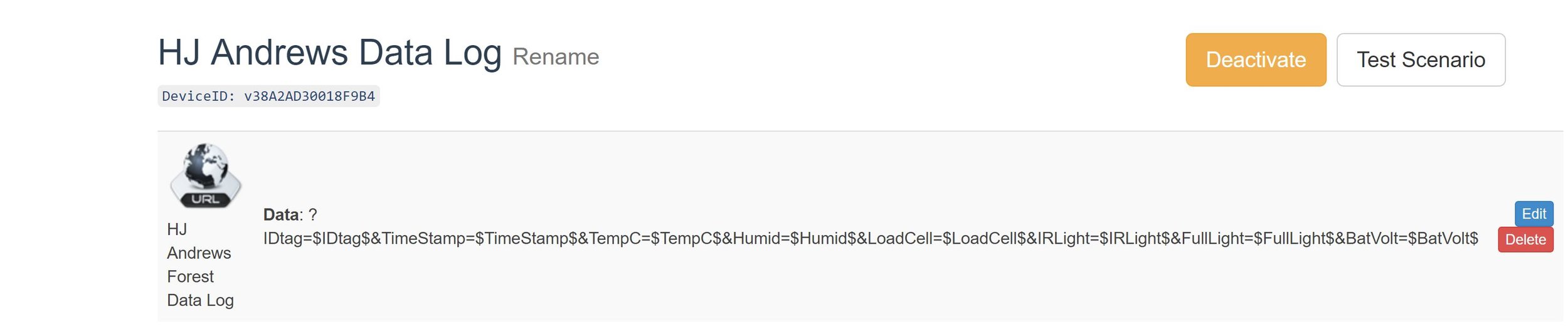
*Make sure to copy your “DeviceID” string that will be generated after setting up the service, you will need it for both preliminary testing in the next step, and later for the Arduino Sketch in Part 4.*
Step Three- Testing API and Google Spreadsheet
Before we move on to the last step, in which we program the Adafruit Feather 32u4 with LoRa Radio Module and complimentary Ethernet Feather Wing which will log data through the web, it would be helpful to test that everything we have done thus far is correct. If we wait to complete the hardware portion then the cause of any errors may be more difficult to track down. Fortunately, we have a simple method of testing our code so far. We can just directly enter some hard-coded pseudo-data into our web browsers address bar and check that our Google sheet is being updated correctly. Here is an example of what you might copy and paste into your browsers address bar.
http://api.pushingbox.com/pushingbox?devid=<<YOUR-PUSHINGBOX-DEVICEID>>&key0=sheetID&val0=<<SPREADSHEET-ID>>&key1=tabID&val1=<<SHEET/TAB-OF-SPREADSHEET>>&key2=deviceID&val2=<<NAME-GIVEN-TO-ARDUINO>>&key3=TimeStamp&val3=50&key4=TempC&val4=200&key5=Humid&val5=80&key6=LoadCell&val6=1000&key7=IRLight&val7=2000&key8=FullLight&val8=3000&key9=BatVolt&val9=4.2
If you like you can even re-enter new fake data with different values for subsequent rows, however, remember you only have a 1,000 requests per day from Pushingbox.com so don’t go crazy! If this procedure did not update your spreadsheet then go back and review Parts 1 -3 of this instructional for errors before attempting Part 4. Congratulations if you have made it this far, the worst is over! (it took me about a dozen times to get all the previous steps correct) Update – the modification of this process and the Google Script since the initial writing of this blog post were primarily to simplify these steps
Step Four – Hardware Set-up and Arduino Sketches
After confirming you were able to push some hard-coded pseudo-data directly from your browser onto your Google Sheet you are now ready for the next step which involves sending data directly from the Feather 32u4 and complimentary Ethernet Feather Wing to Google via Pushingbox over an Ethernet connection. Before you can upload and run the included Arduino sketch to the Feather Board you must complete the following three steps.
Hardware
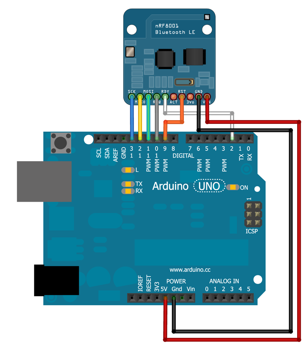
1. Wiring the Feather 32u4 board to the Ethernet FeatherWing: a guide on how to do this can be found on the adafruit website here, as well as one of my previous posts, found here.
Software(1):
2. There are a few steps to set up your Arduino IDE to work with your Feather 32u4 board.. These steps include downloading the necessary libraries and configuring the Arduino IDE (1.6.4 or later) with the correct Feather Board package. Many of you will have already installed all the software you need, for those that have not, below are links to retrieve the needed libraries and the Feather 32u4 board support package.
The two required libraries for our particular sketch:
- https://github.com/PaulStoffregen/RadioHead/blob/master/RH_RF95.h (Handles all components of the LoRa Radio Function, Not needed for all projects)
- https://github.com/adafruit/Ethernet2
- Optional (If interested in SD card back-up)
- https://github.com/adafruit/SD/blob/master/SD.h
Two great tutorials to walk you through getting the correct Feather 32u4 board and Ethernet FeatherWing package installed into the Arduino IDE if you haven’t done this already:
Software(2):
3. You are now ready for the final step of the project, you need to copy and paste the included Arduino sketch, customize it for your device, and then upload the sketch onto your Feather 32u4 board and Ethernet FeatherWing. Update – that sketch is now out of date, refer to the Loom Library instead for the corresponding updated code and process.
A) Your MAC Address (Found in Ethernet packaging)
B) Your Static IP address (May need to be given by IT admins)
C) Your Pushing box Device ID (devid)
That’s it, you’re done! If everything was completed correctly your output will look something like the picture below:
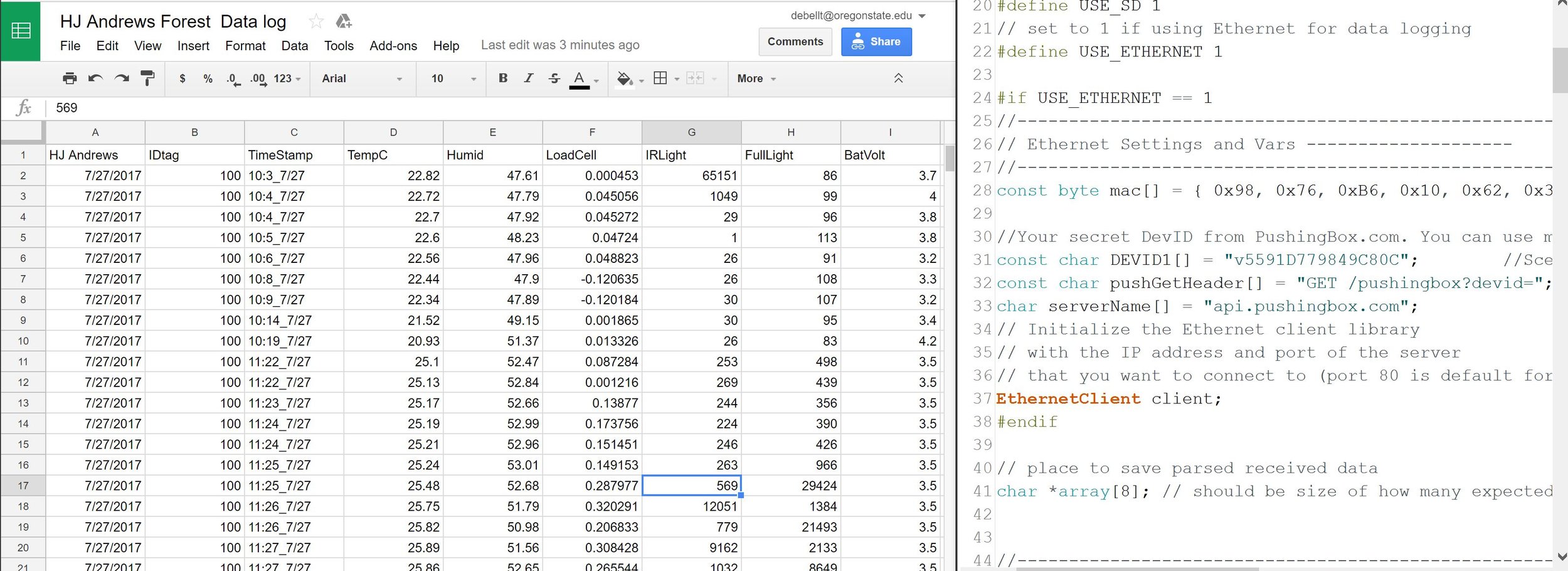
Populated Google Spreadsheet (left) and Ardiuno IDE with example code.
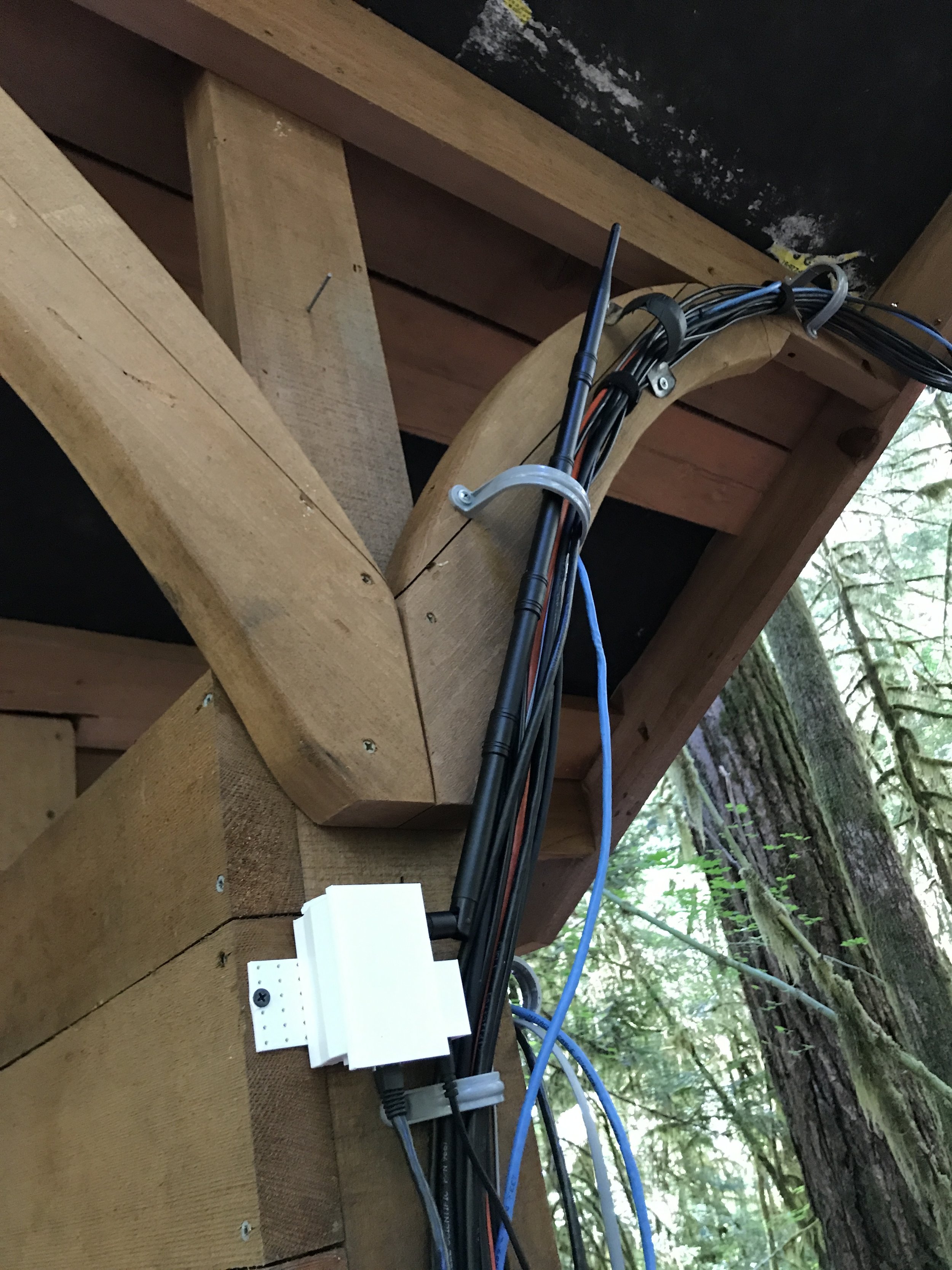
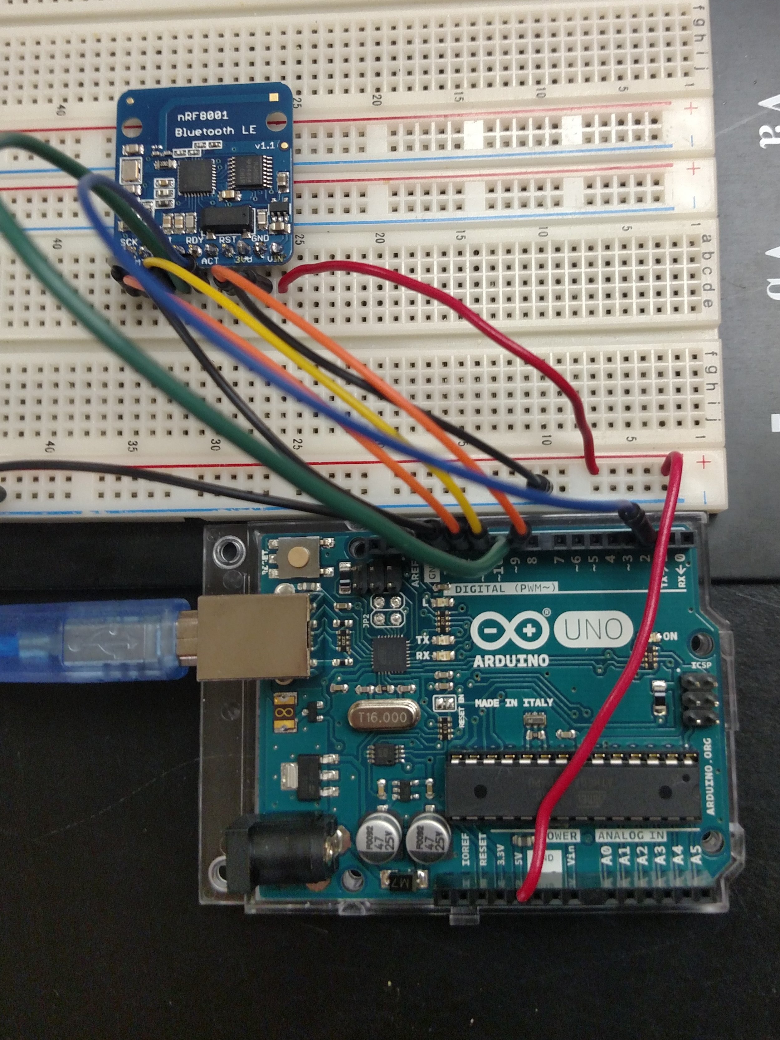
Final Receiver and Ethernet data logger set-up.
– Tom DeBell, Beginning Researcher Support Program Researcher