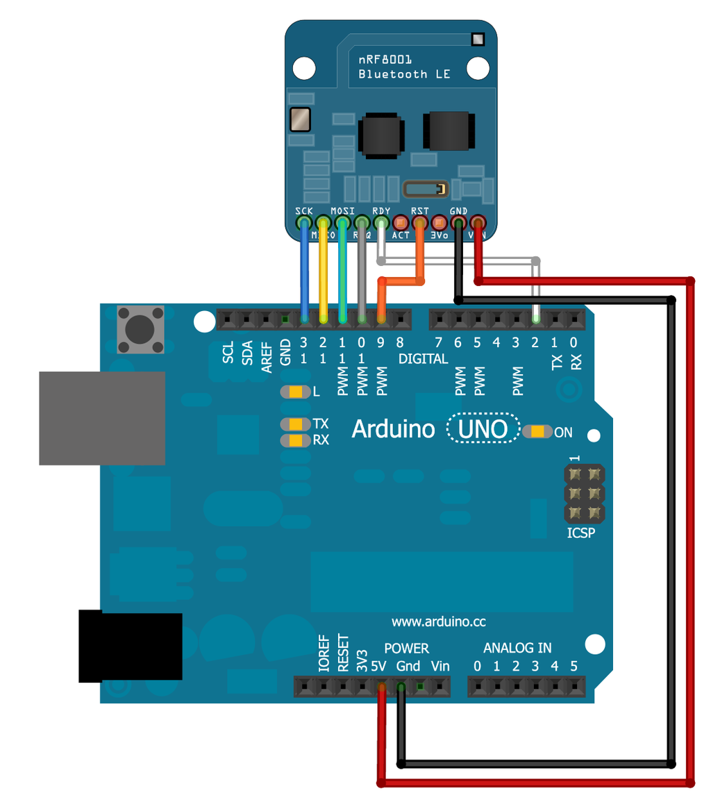
Note: The nRF8001 sends out packets of data, 20 bytes at time. Keep this in mind if you want to send a lot of data it will be packetized into chunks of 20. You can of course send less than 20 bytes.
Exploring Mobile Interface
After initial setup and software tests, I was able to explore the Adafruit developer smart phone application found in the android market, “BlueFruit LE”. (APK file linked here)
Much like Serial you can use the .write and .print functions allow us to send data out to the connected device:
Features included in Bluefruit LE App
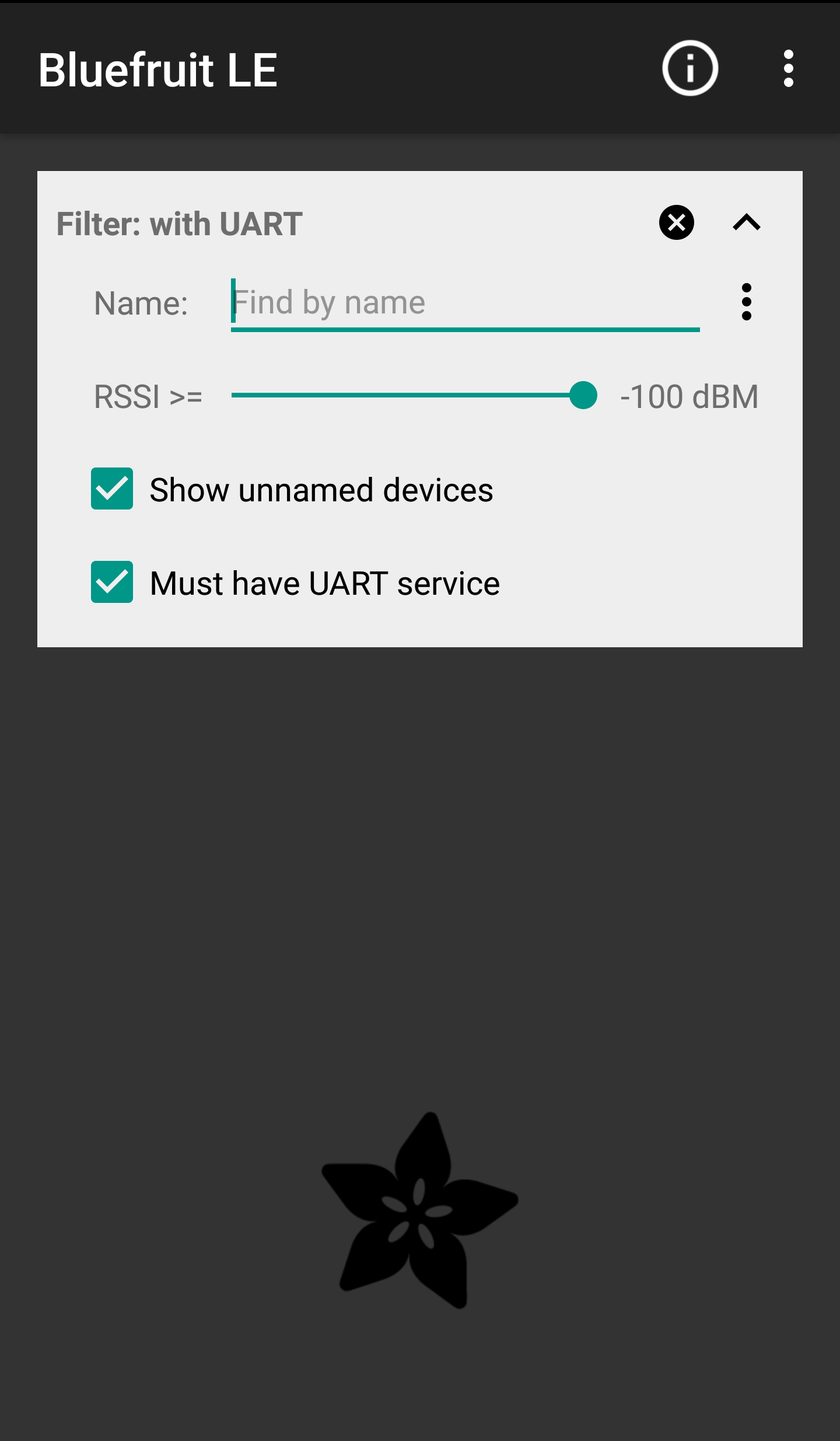
Home screen of the “Bluefruit LE” smartphone application
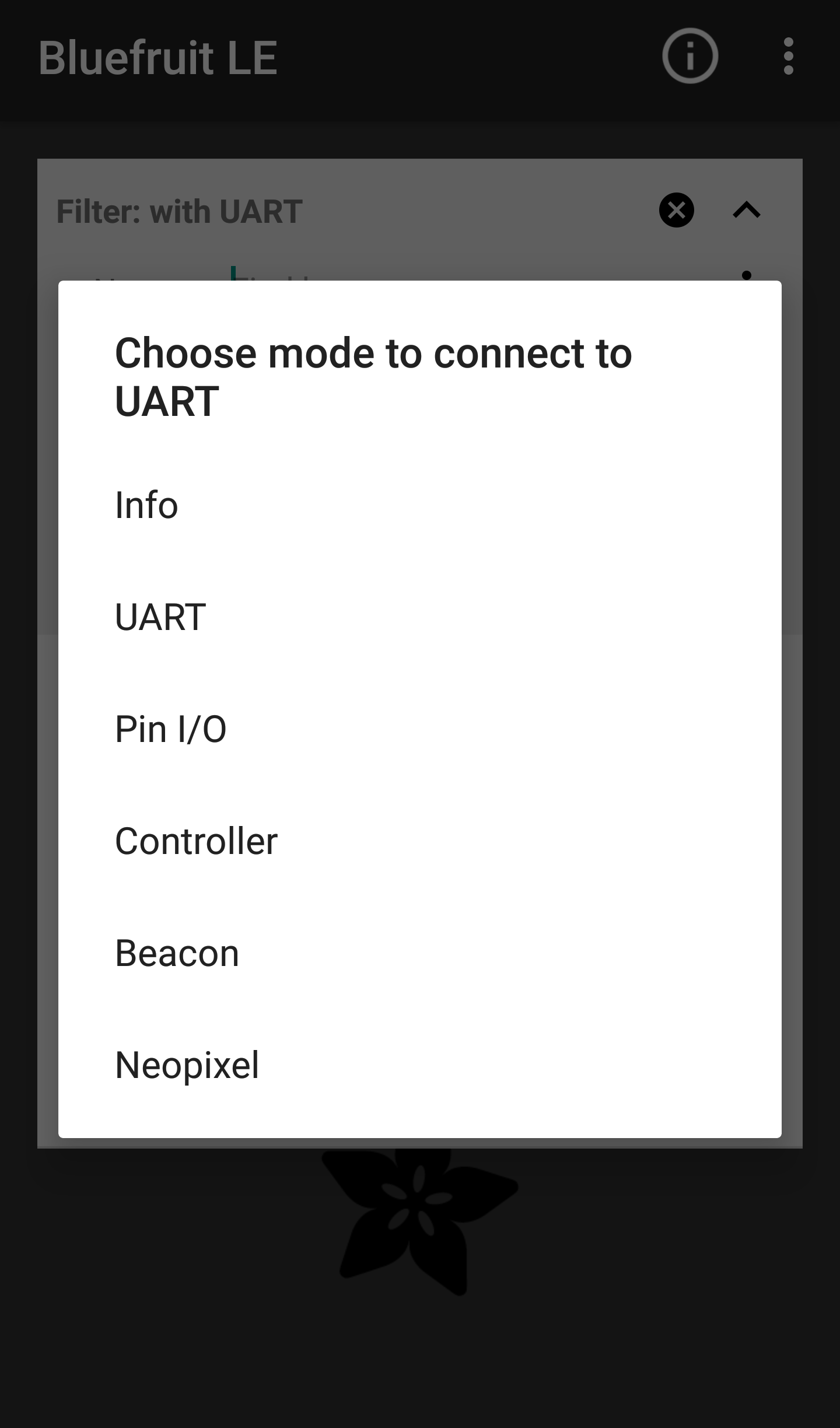
Display after connection with Bluetooth module
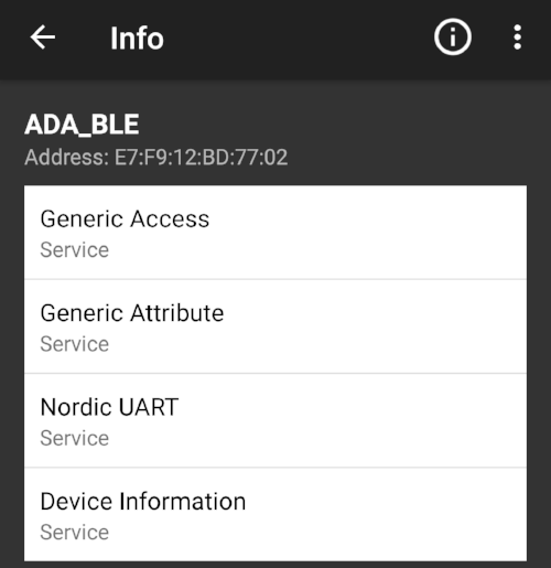
Info
Displays MAC address and other relevant Device Information
UART
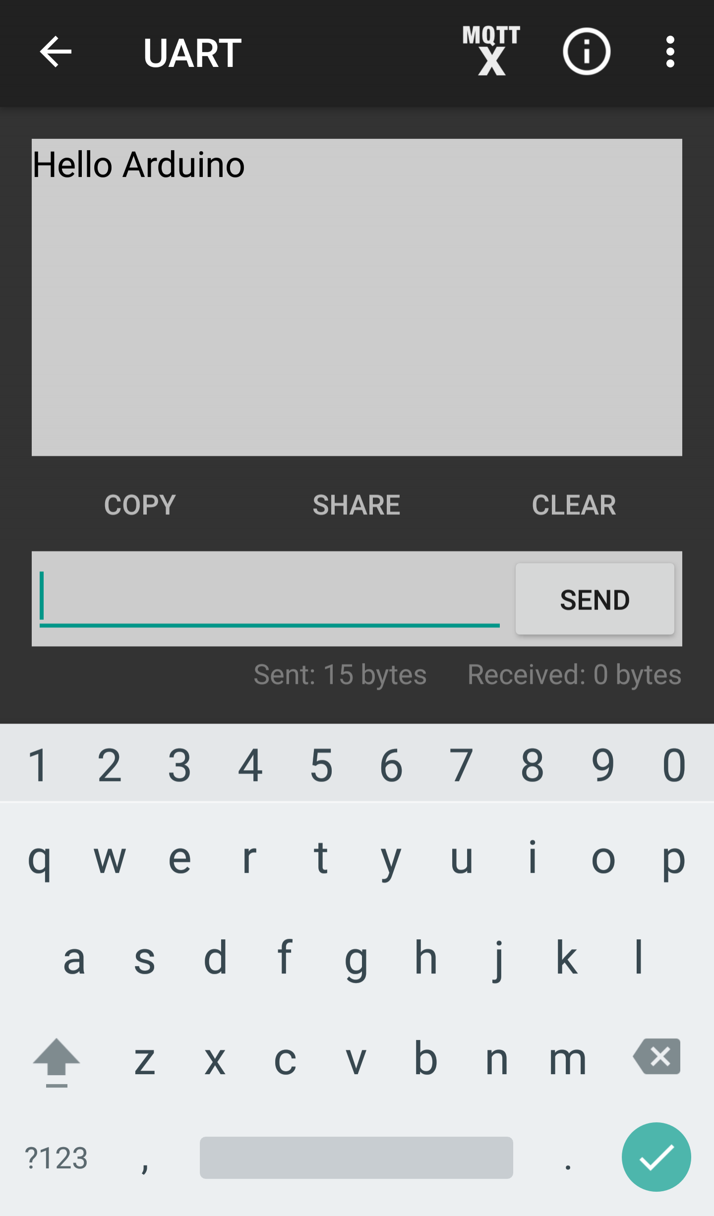
Screenshot showing a message being transmitted to the Arduino from my smartphone
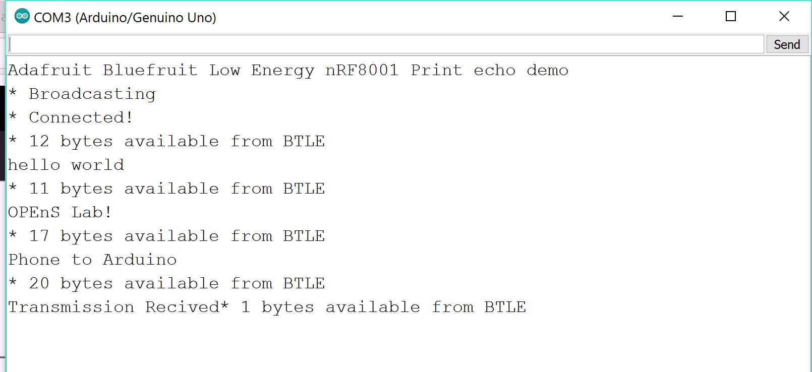
The “UART” function allows a basic text message interface from smartphone to the Arduino Series monitor. However, after testing it was apparent that although the application allows infinite characters of transmission, the messages are broken apart into 20 character fragments due to the data transmitting capabilities of the bluetooth chip.
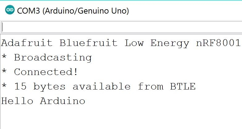
Snip showing successful reception of the message from my smartphone to the Arduino seriel monitor
Pin I/O
The Pin I/O section of the mobile phone application allows the user to control input and output of pins (both analog and digital) on Arduino shield. However, this particular function required significant code modification in order to allow functionality on Android enabled devices. Once the code is finalized it will be published and linked here. In order to display this faciniating functionality a small demo was contructed in order to deminstate the smart phone interfaces capabilities.
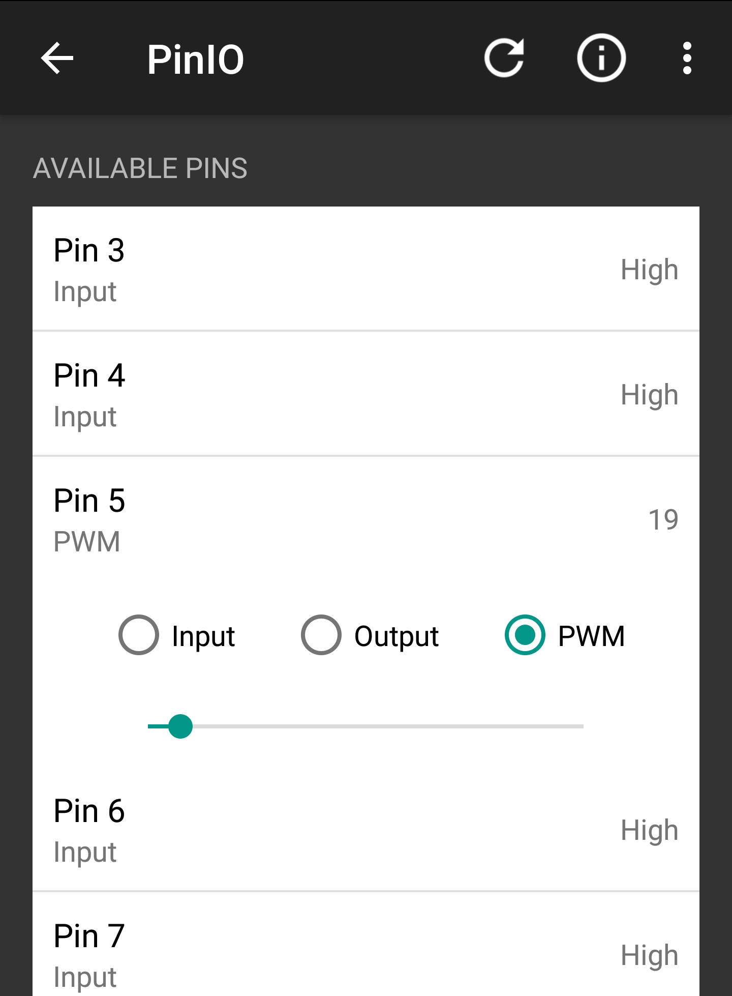
With just a slide of my finger I am able to modify the signal strength being admitted from the Arduino
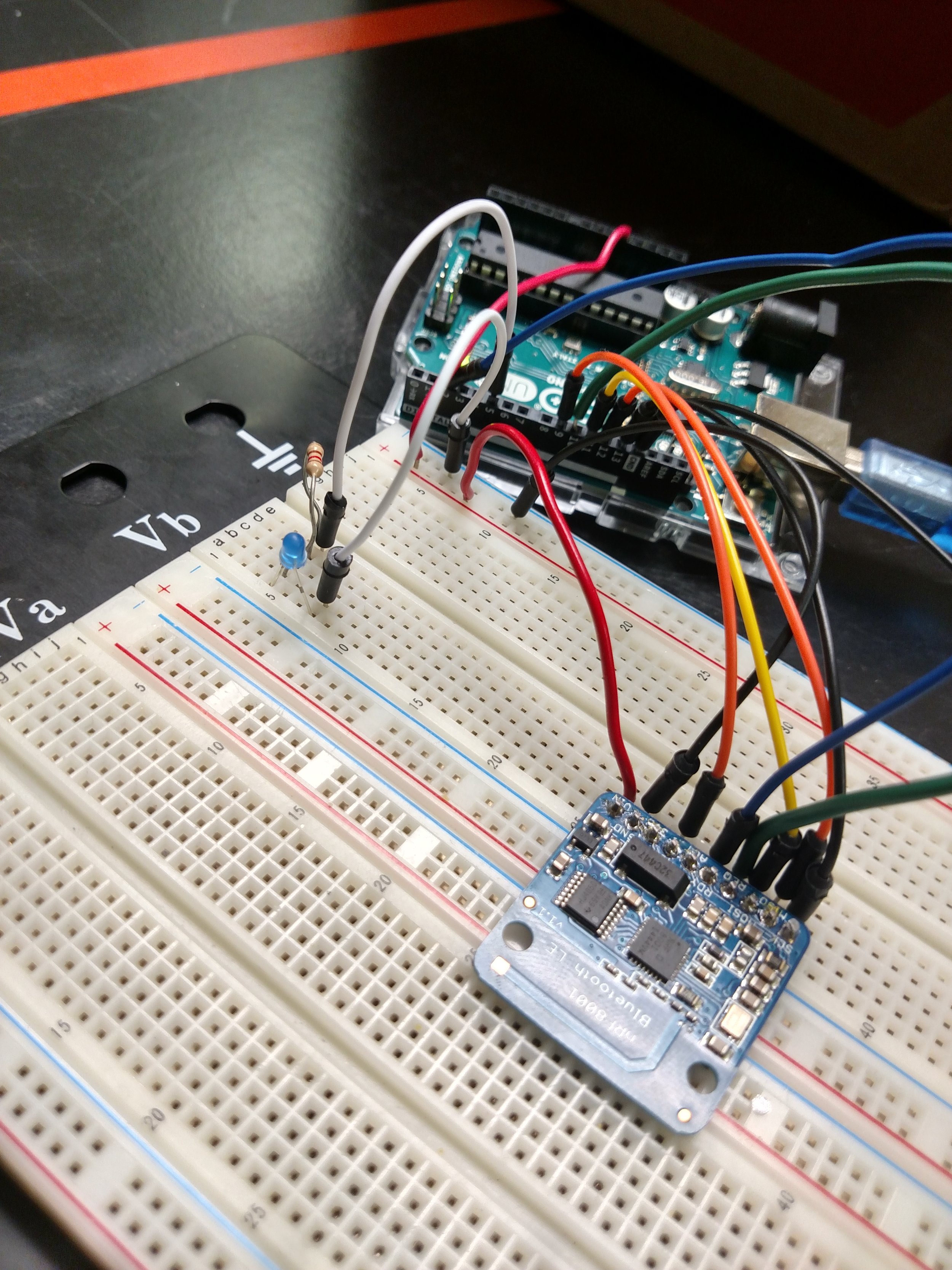
The Blue LED is only lightly illuminated due to low PWM signal as specified by the photo on the left
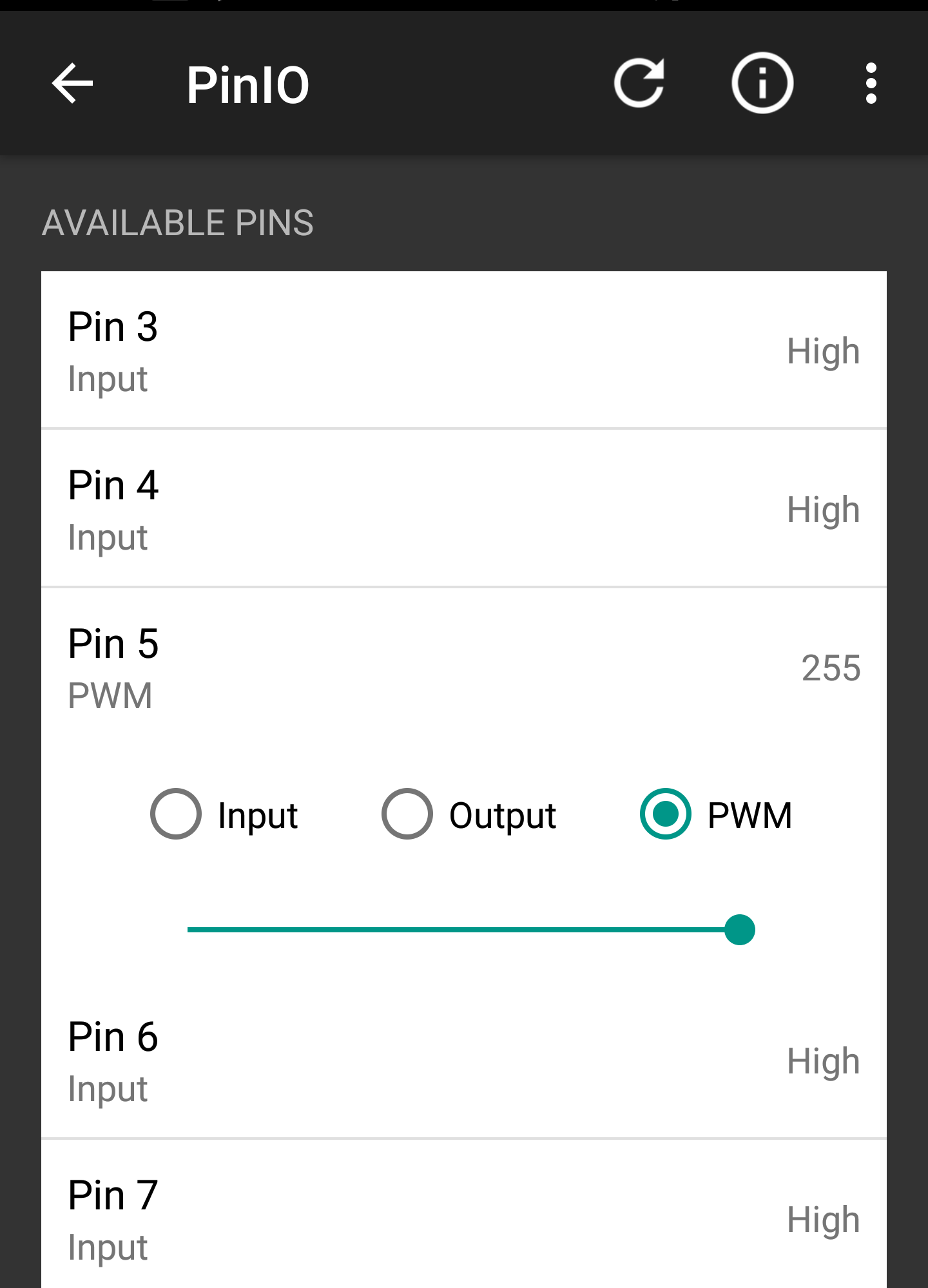
The PWM slider was moved all the way to right to allow for maximum signal strength
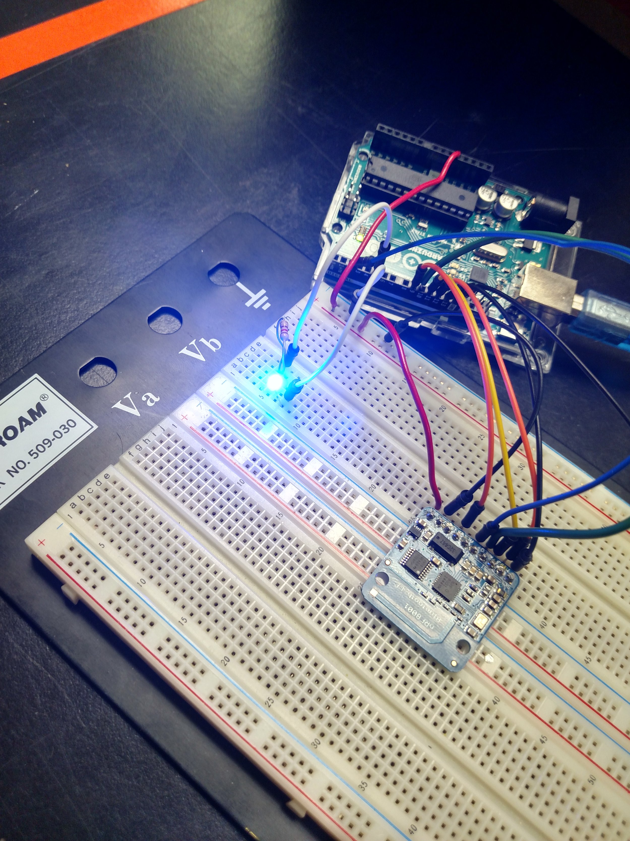
The increased signal strength as shown on the left caused the LED to shine brightly
This section of the Bluefruit LE application appears to be very useful, unstable and will require further explanation.
Controller
Streams sensor data from smart phone sensors (Quaternion (6-axis accelerometer), Accelerometer, Gyro, Magnetometer, Location)
Beacon
Puts smartphone in a state to receive pop-up text messages from serial monitor up to 20 characters
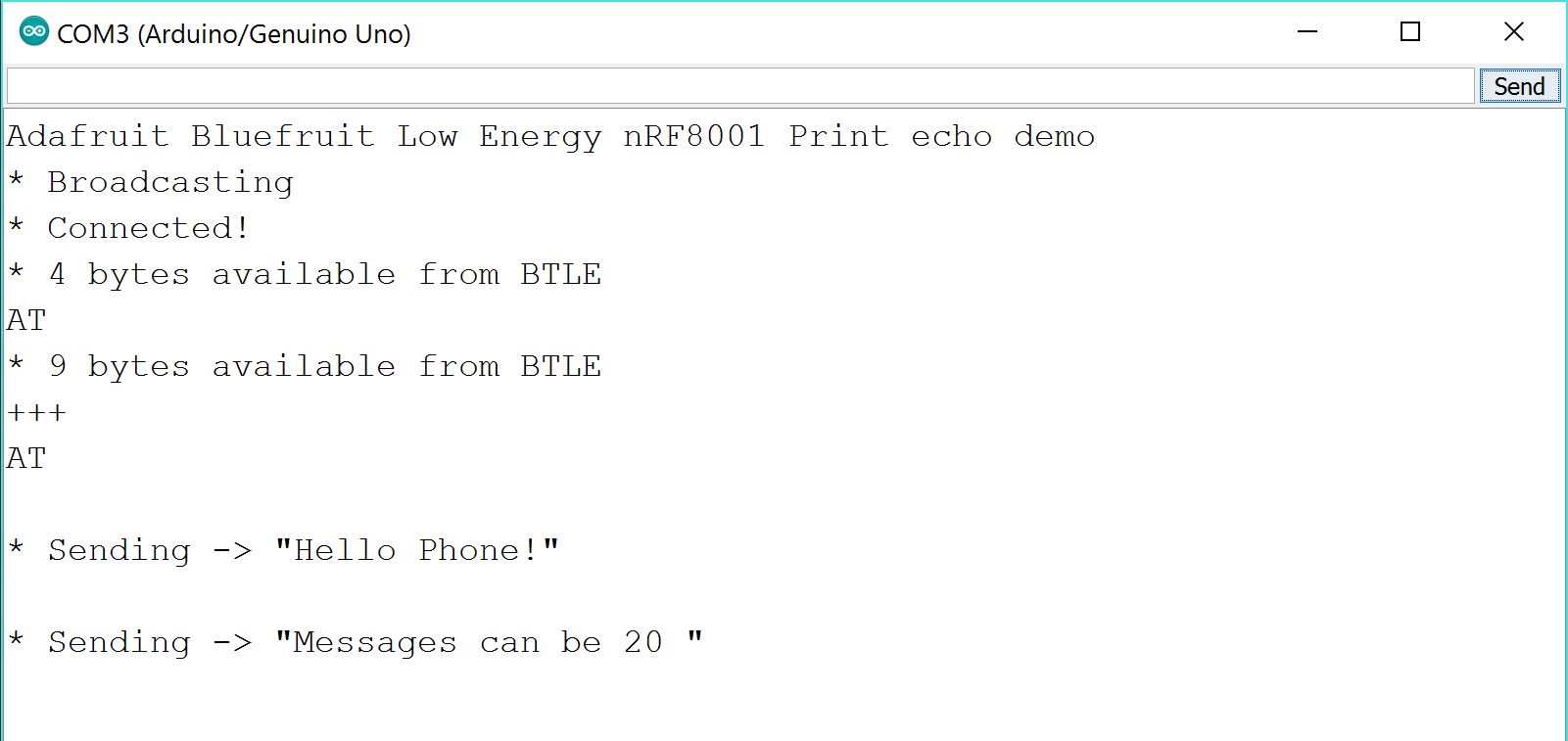
Snip from the Arduino Serial Monitor during transmission testing

Screenshot of the recived message from the Ardiuno

Messages are restricted to only 20 characters
Neopixel
Needs further exploration.
Conclusions
**Initial testing of connectivity shows an approximate range of 20 feet for reliable signal strength.**
After initial testing it would appear that the Pin I/O will have the most practical capabilities and research of its functionality will continue.
– Tom DeBell, Beginning Researcher Support Program researcher