Initial setup for this project began early this week starting with soldering header pins onto the nRF08001 Bluetooth LE (Low Energy) breakout board so that a physical connection could be made with an Arduino Uno module to begin testing. A valuable resource that helped getting started can be found at adafruit.
The wiring of the Bluetooth board to the arduino was done as follows.
Wiring Schematic
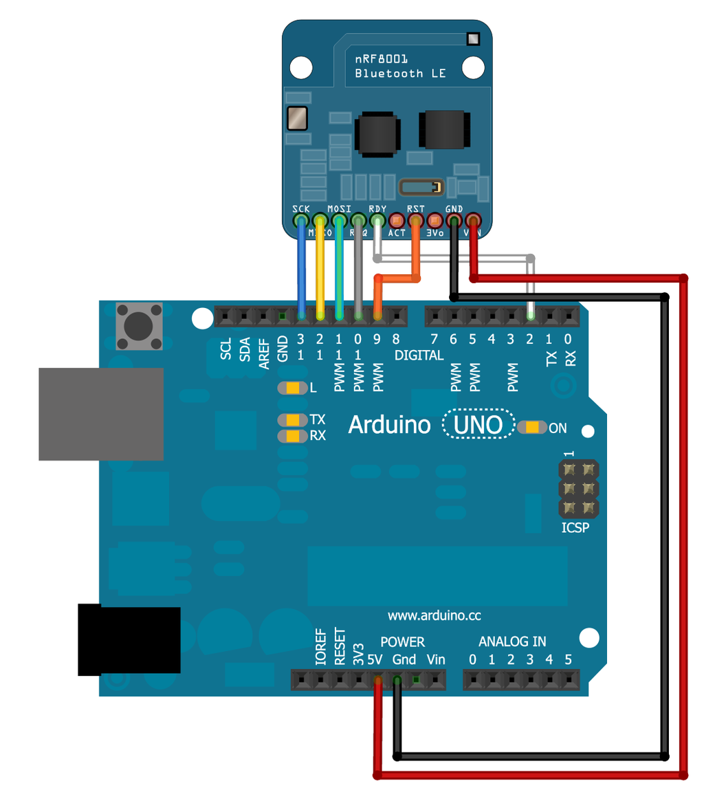
Wiring Schematic via Adafruit
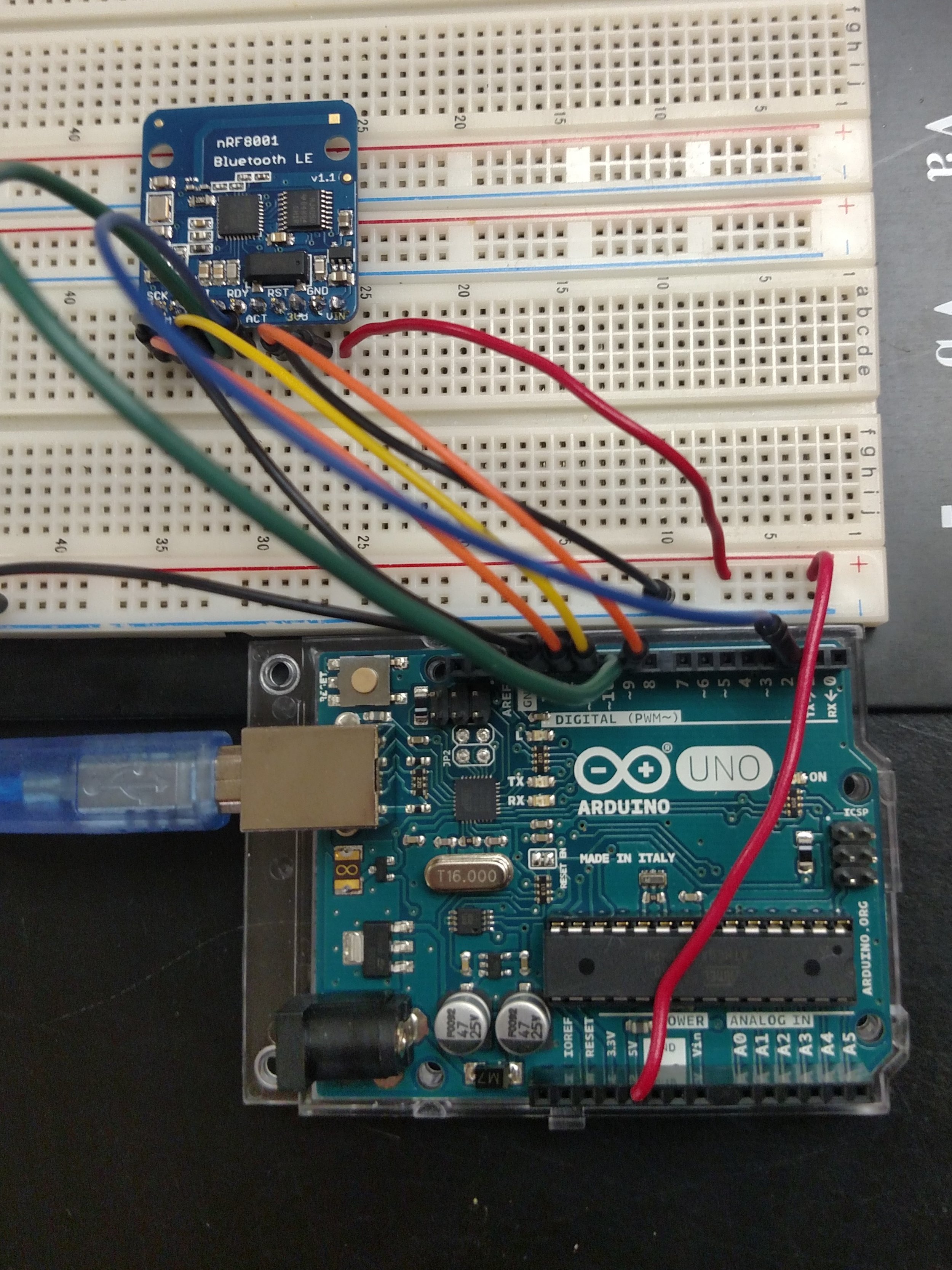
Wiring completed on April 5th to begin testing
- VIN connects to the Arduino 5V pin (Red Wire)
- GND connects to Arduino ground (Black Wire)
- SCK connects to SPI clock. (Blue Wire)
On Arduino Uno/Duemilanove/328-based, thats Digital 13.
On Mega’s, its Digital 52 and on
Leonardo/Micro its ICSP-3 (See SPI Connections for more details) - MISO connects to SPI MISO. (Yellow Wire)
On Arduino Uno/Duemilanove/328-based, thats Digital 12.
On Mega’s, its Digital 50 and on
Leonardo/Micro its ICSP-1 (See SPI Connections for more details) - MOSI connects to SPI MOSI. (Teal Wire)
On Arduino Uno/Duemilanove/328-based, thats Digital 11.
On Mega’s, its Digital 51 and on
Leonardo/Micro its ICSP-4 (See SPI Connections for more details) - REQ connects to our SPI Chip Select pin. We’ll be using Digital 10 but you can later change this to any pin. (Grey Wire)
- RST connects to Digital 9 – this is for resetting the board when we start up, you can later change this to any pin. (Orange Wire)
- RDY is the interrupt out from the nRF8001, we’ll connect to Digital 2 but be aware that if you want to change it, it must connect to an interrupt capable pin (see this Arduino page for which pins are interrupt-capable. Digital 2 is OK on Uno/Leonardo/Micro/Mega/etc.) (White Wire)
- Note: Wire colors refer to first wiring diegram
Initial Testing
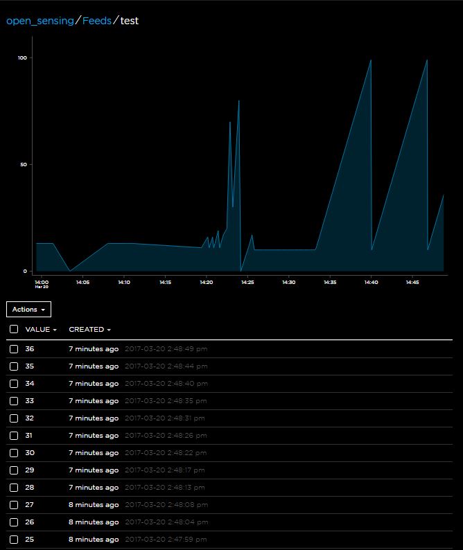
After wiring was completed testing of bluetooth transmissions and functionality began with positive initial results. By running a sample arduino code found on GitHub we were able to communicate to the arduino via the “Bluefruit LE” android application and likewise was able to transmit data from the command line of the arduino workspace directly to a smart phone via the bluetooth module. Further Testing will contiuno next week.
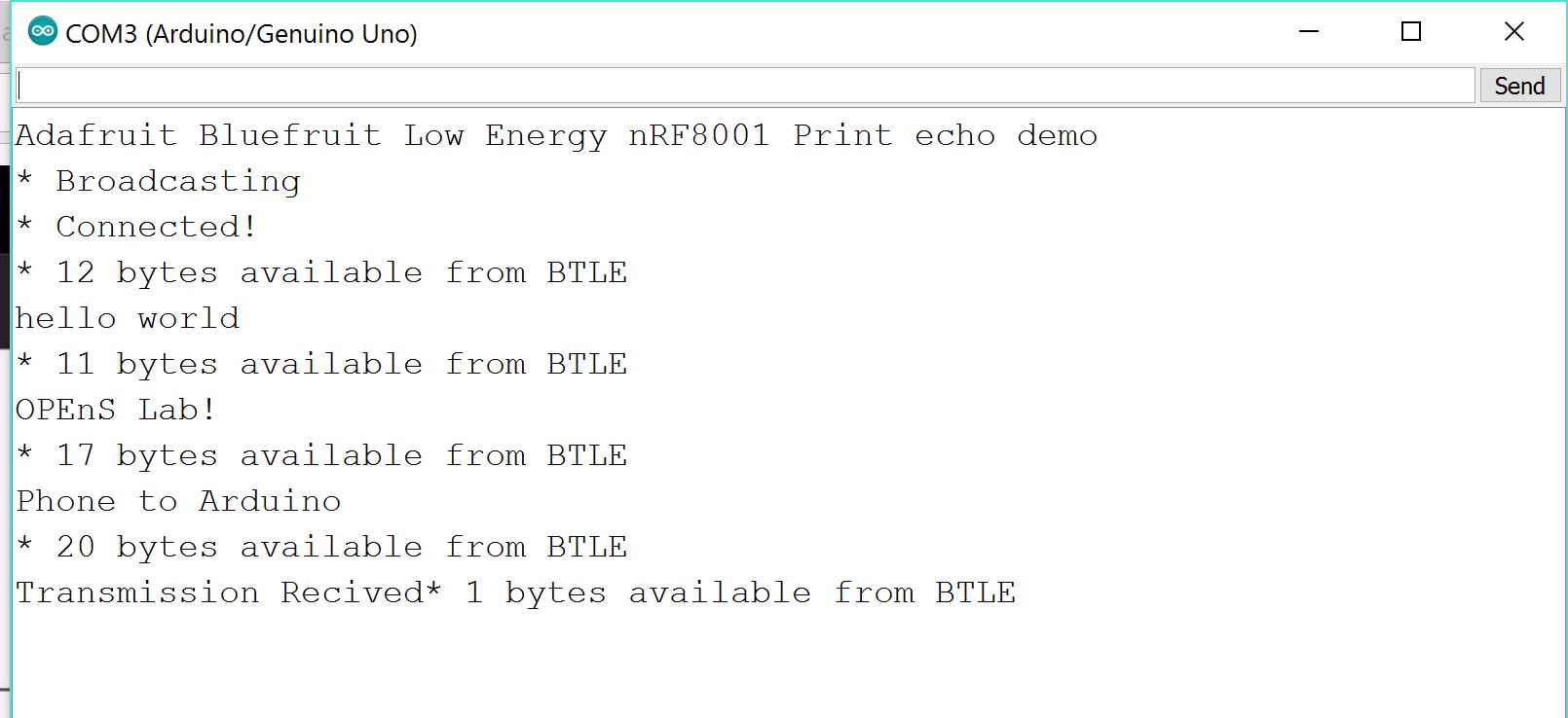
Snip from the Arduino Serial Monitor during testing
– Tom DeBell, Beginning Researcher Support Program researcher