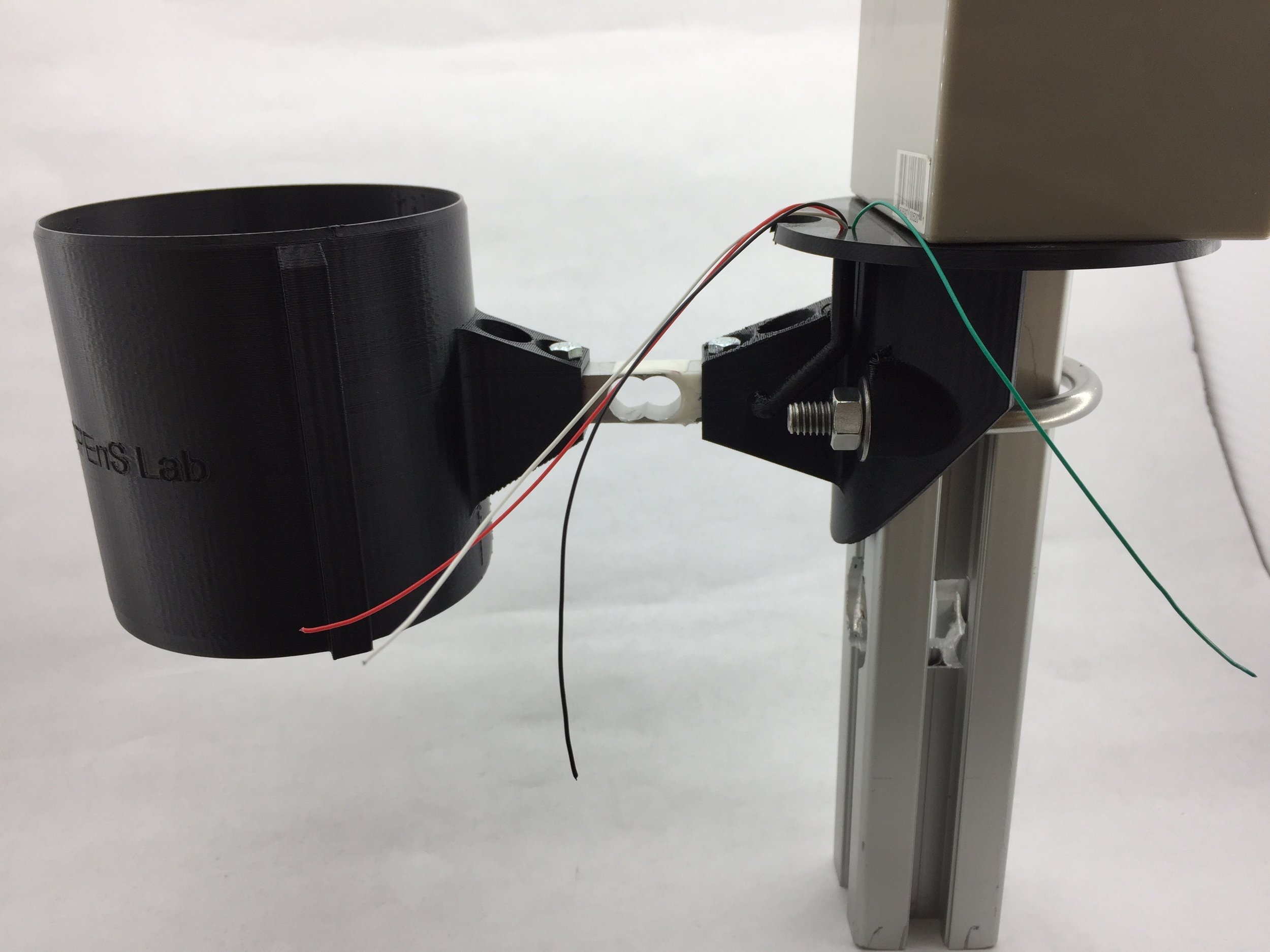
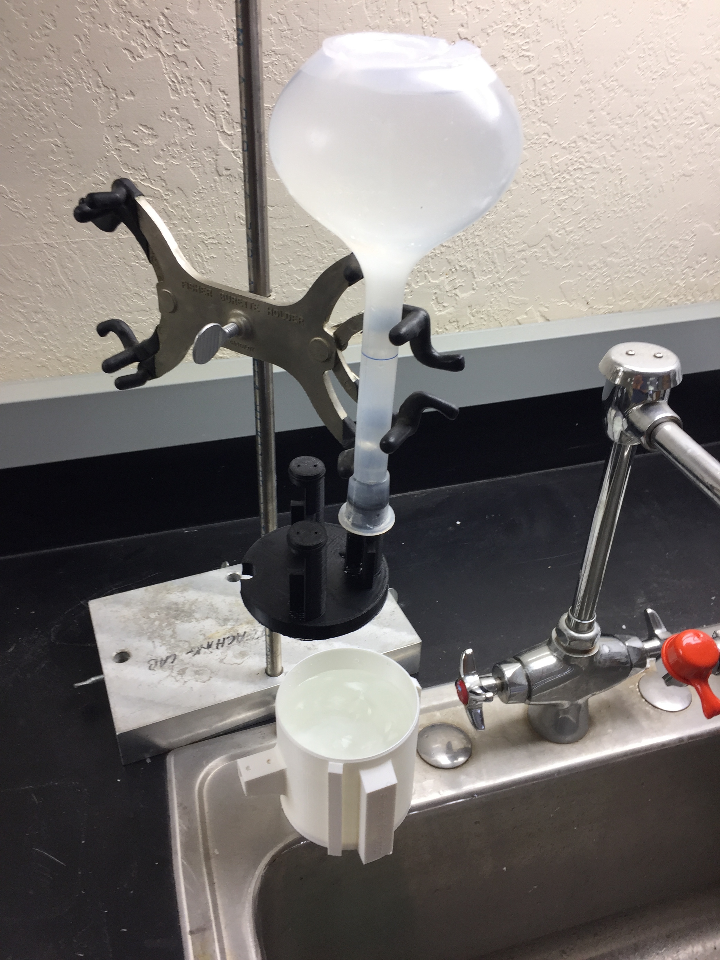
The main body of the pole attachment has been done for some time, but getting the wires of the strain gauge through the tube was the lasting thing remaining. The main trouble was that the wires would only go through a section of the guiding tube and then get stuck. They now go through all the way very smoothly.
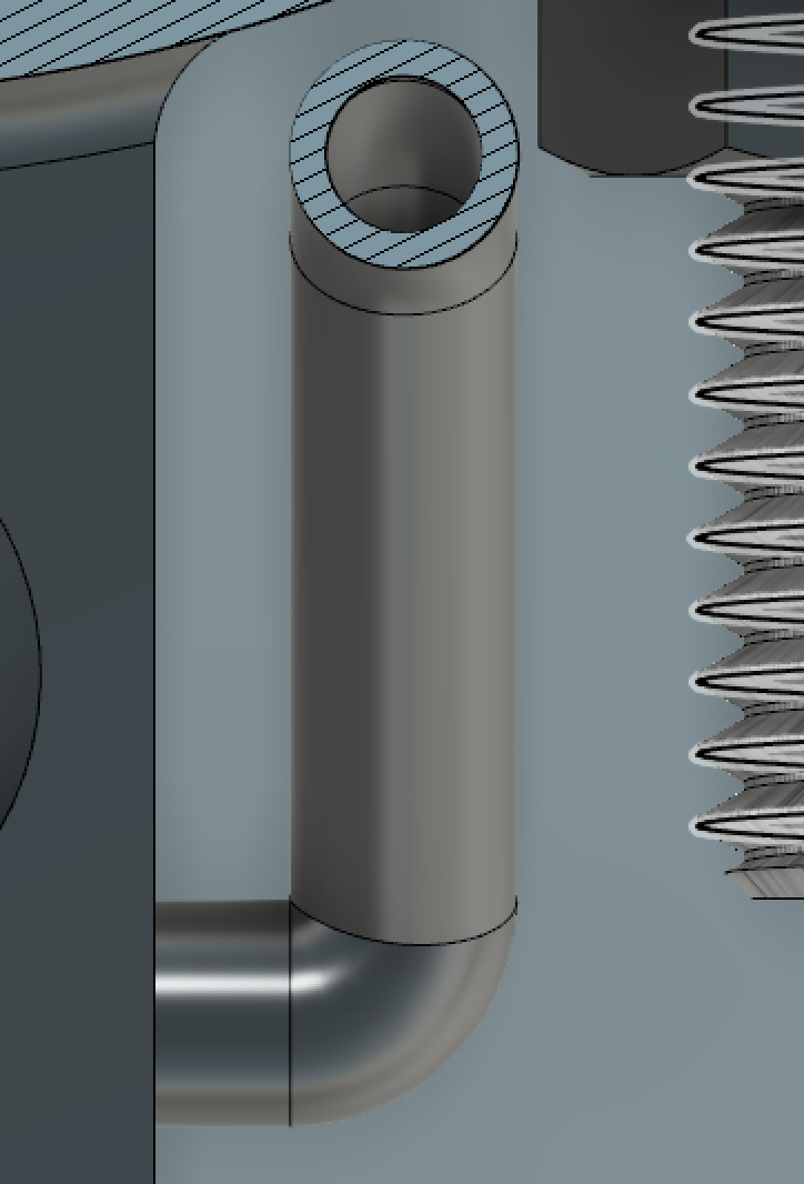
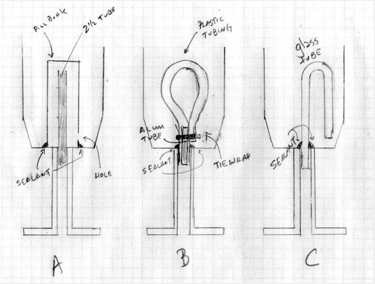
First design with 90 degree corner
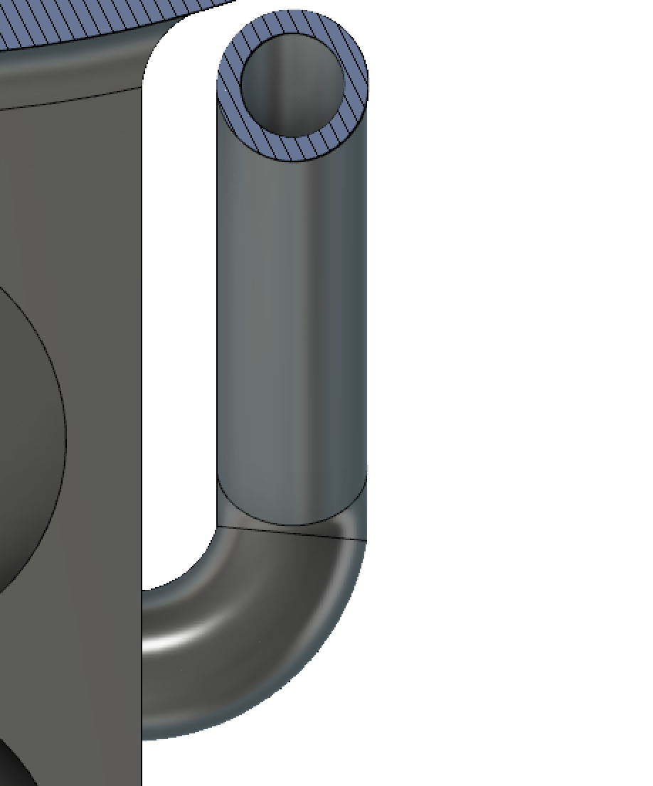
Second iteration with a smoother path
The first iteration had a right angle that impeded the passage of the wires. It would only get through the hole but not through the corner. The logical next step was to reduce the amount of curvature that the wires had to go through. To work around this problem, I inserted a piece of wire through the top hole and soldered all the tips of the wires from the strain gauge together. I then pull the wire, and since all the wires were soldered to it, they all came through. This worked well but is not ideal. This is why further development was needed.
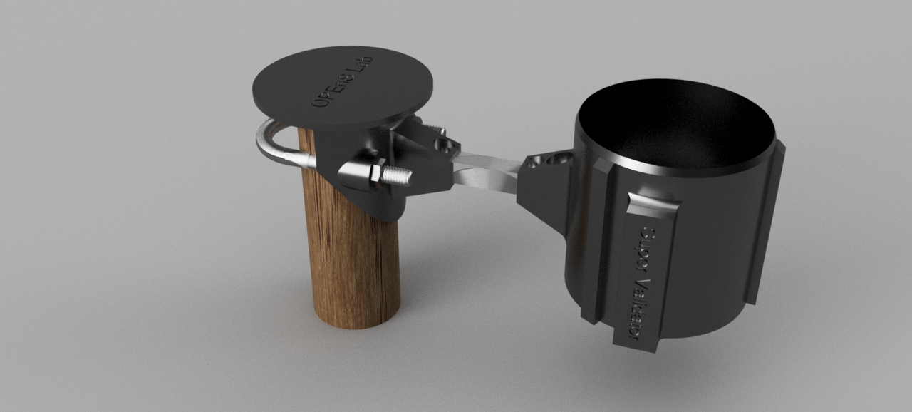
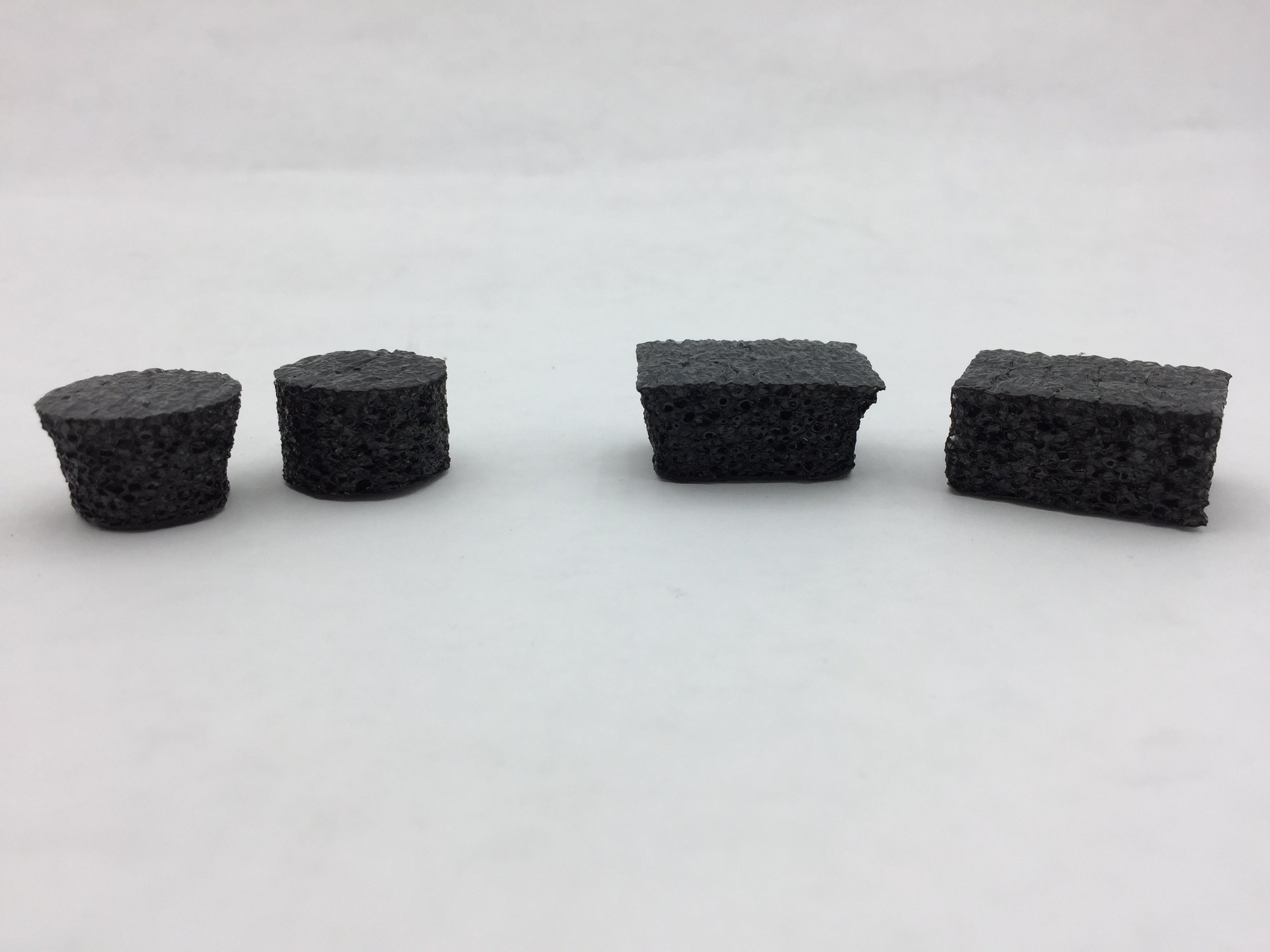
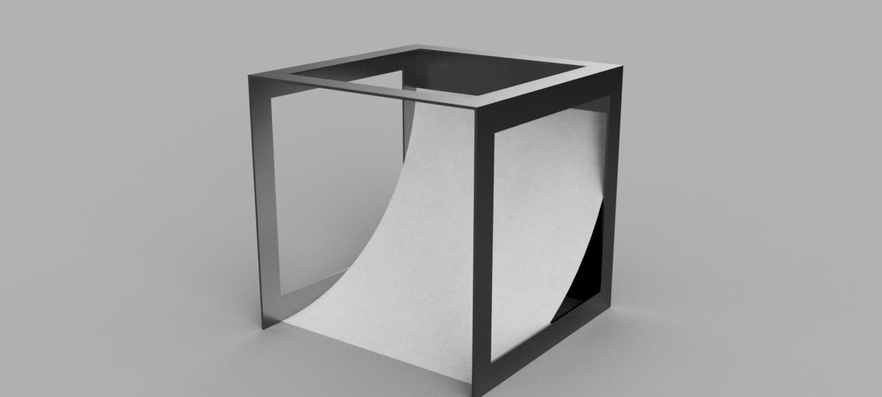
The final design was different than what I was initially thinking about. There is no curve to the side instead there is loft coming from the side of the block in the form of a rectangle to a circle. This design makes it so that the wires don’t have to go through corners.
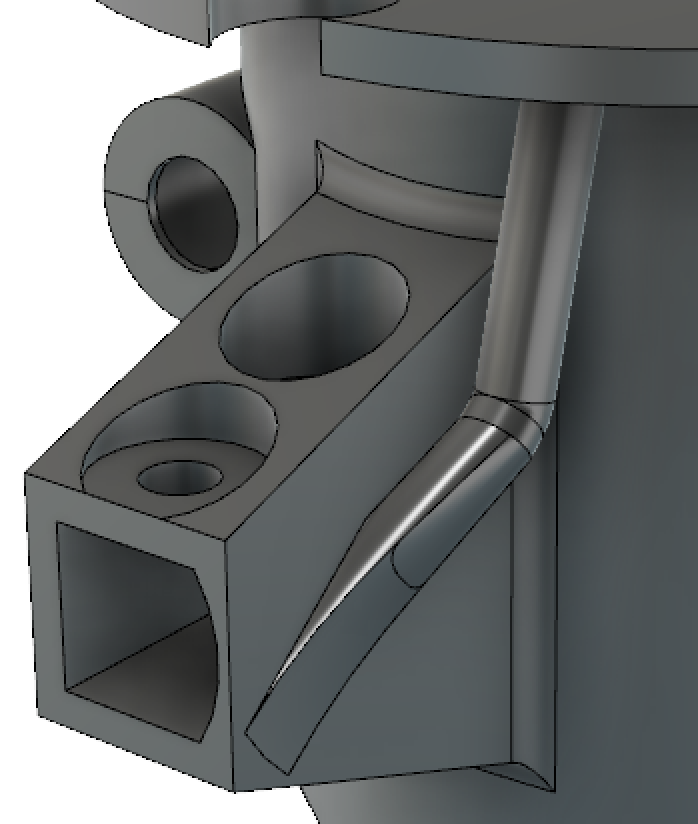
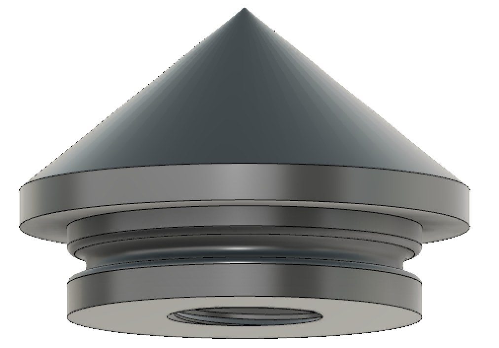
Final design of wire guide
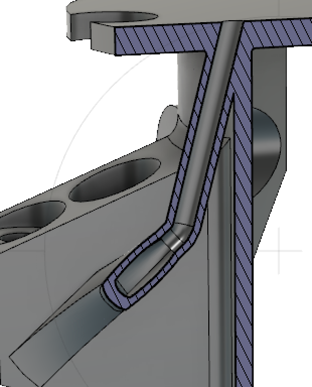
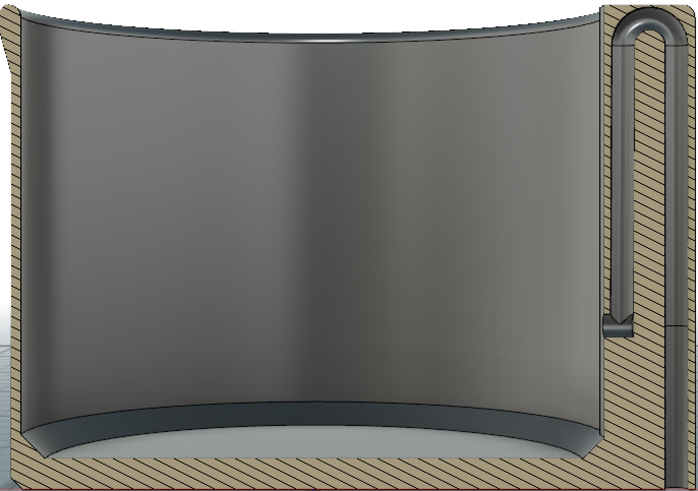
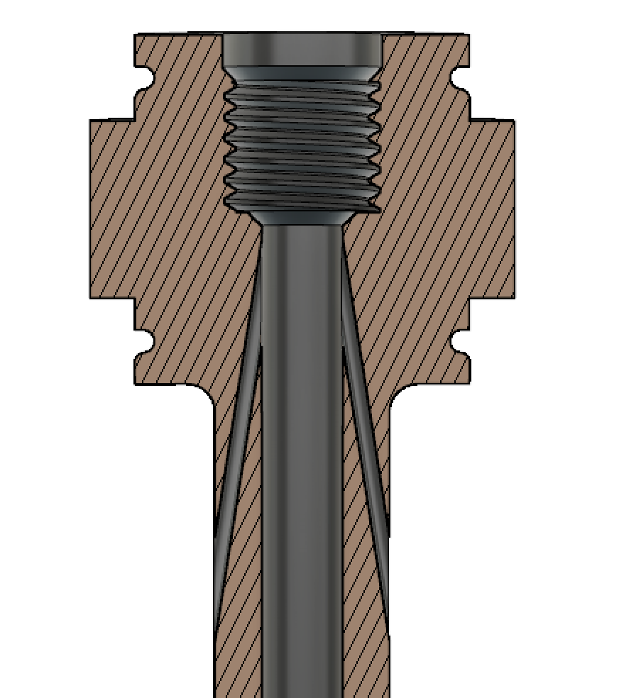
Cross section of wire guide
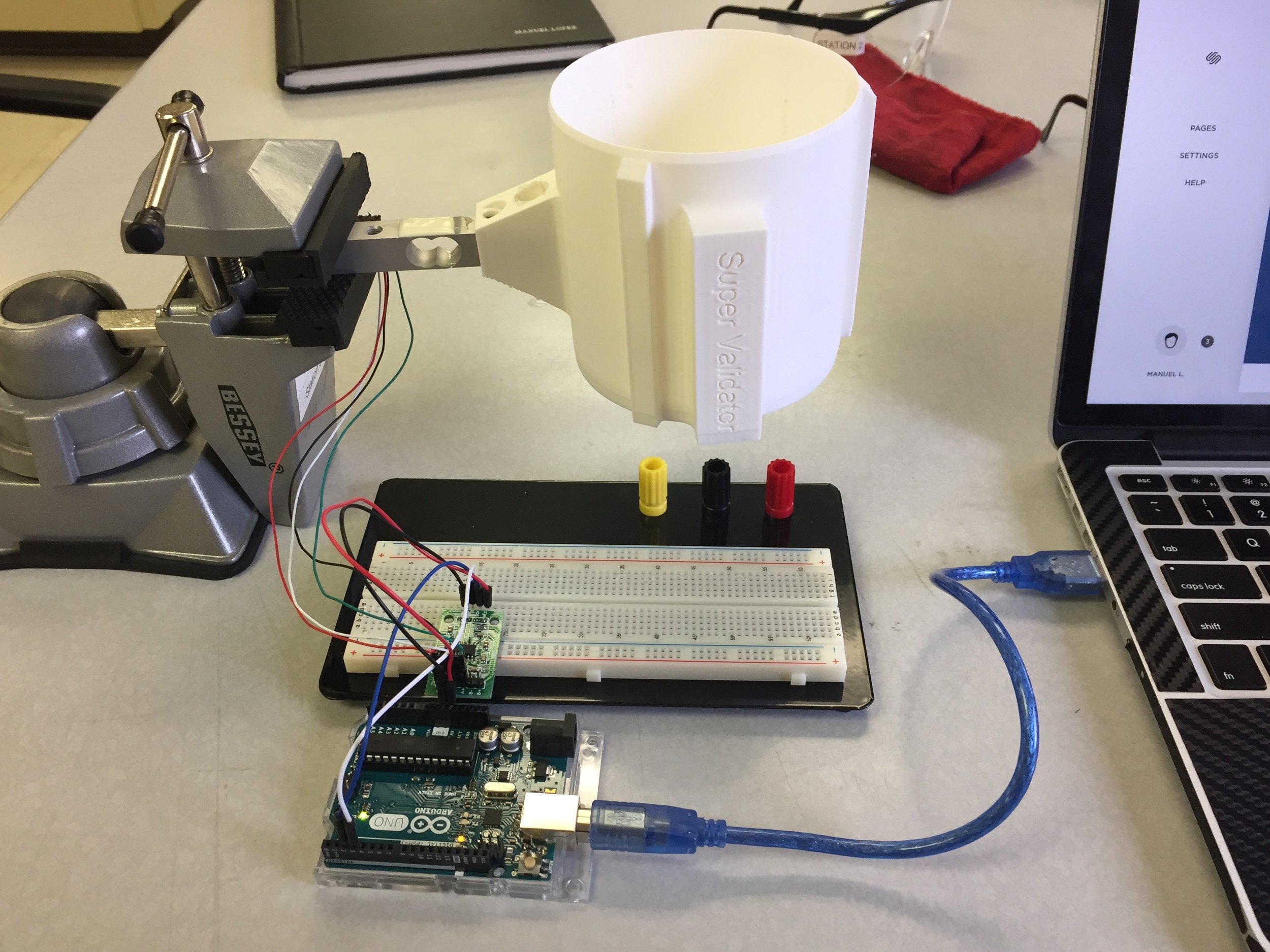
This is the iteration that will be used for testing in Kenya. Here is an interactive model of the piece:
Polev52 By Manuel Lopez Modelo »