
Abstract
I have created a new version of the evaporometer where everything is stacked. The main reason for this is to shade the strain gauge from the sun. In this post, I will summarize the design of the evaporometer and show some images of the early iterations of this design.
Design
Electronics Case

Electronics case CAD
The image above shows the CAD of the casing of the electronics; inside it will also hold a 6000mAh battery. This part will have an attachment, like the previous versions, where it will have a slide mechanism for easy setup. This version also has a cork gasket so that it will have a better seal between this piece and the cap making it weatherproof.
Electronics Cap
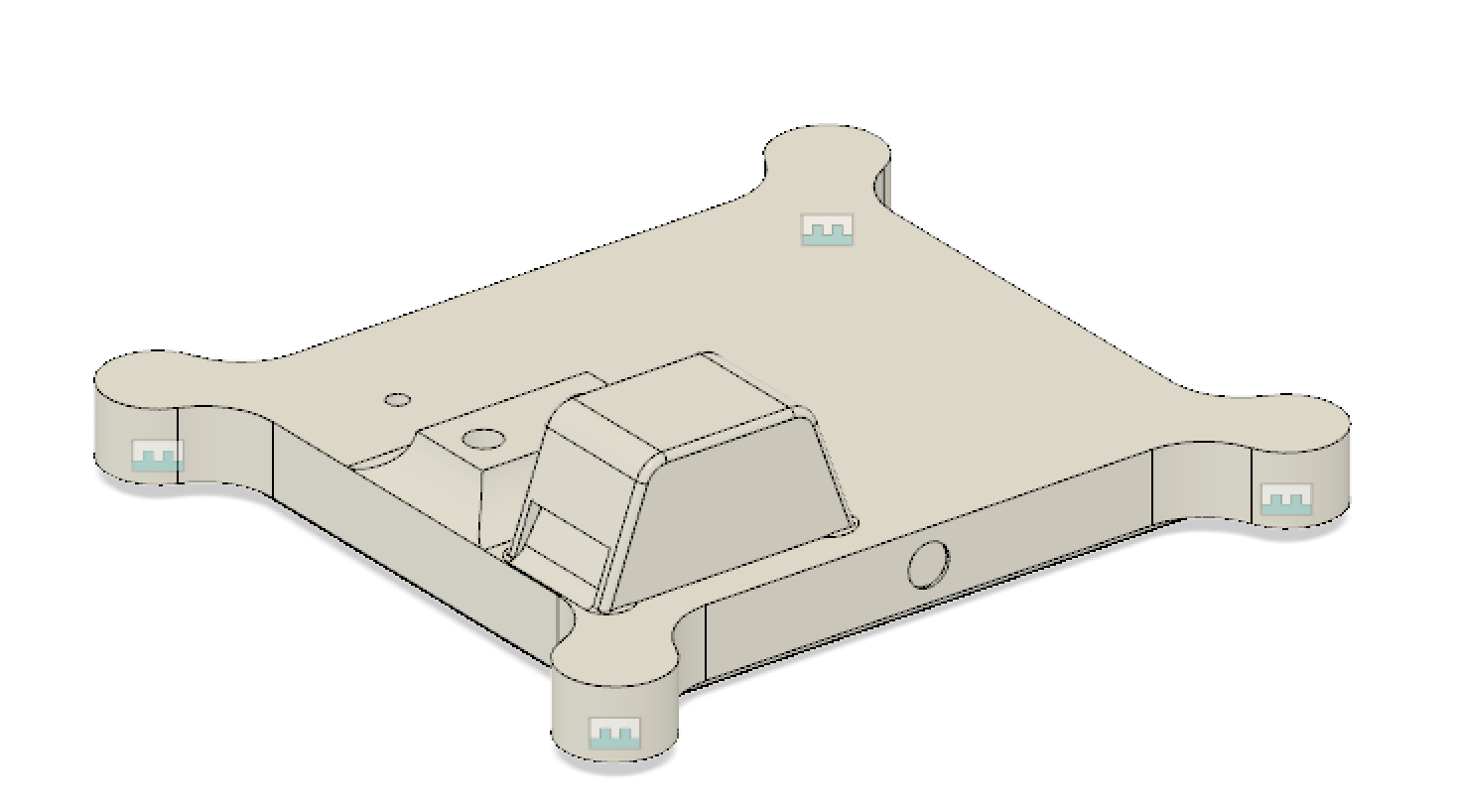
Electronics cap CAD
The image above shows the important elements of the cap. The first, the strain gauge will connect directly to the cap. The second, the little hump that is close to the edge will allow airflow through a slit that will be going right next to the SHT31 sensor, allowing for Humidity/Temp data. And last, the little hole that will allow for the wiring of the strain gauge to go to the microcontroller.
Water Container
The water container was changed much from the last iteration. This iteration alllows for the strain gauge to be connected from the bottom.

Water container CAD
The container is actually made from two pieces. The first piece is bolted to the bottom of the container and then that same piece gets bolted on the strain gauge. The image above shows the assembly of the pieces.
ETA Attachement
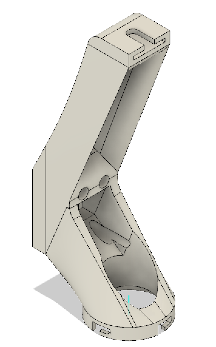
ETA attachement CAD
The image above is the attachment that will hold the two TSL2561 sensors. The bottom sensor will have attached using a twist lock mechanism and the top will be on a swivel.
ASSEMBLY
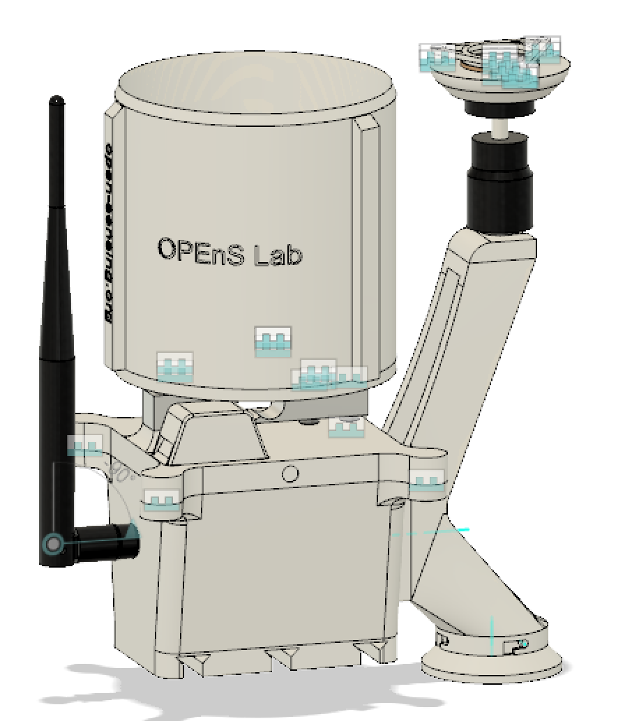
CAD Assembly
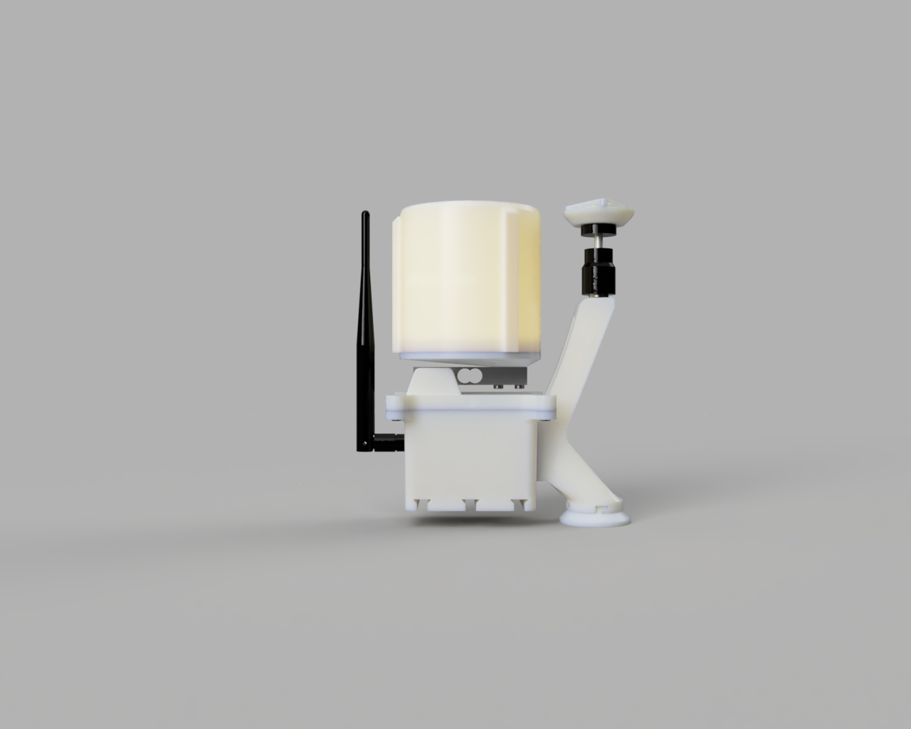
CAD Rendering