As light as a Feather

Abstract: We are trying to improve the capabilities of the HyperRail to have wireless communication with other sensors, and in order to do that we needed to upgrade the microcontroller. I’ve tested the Feather M0 LoRa with the HyperRail and it works. This post is a summary of the integration of the new microcontroller. 

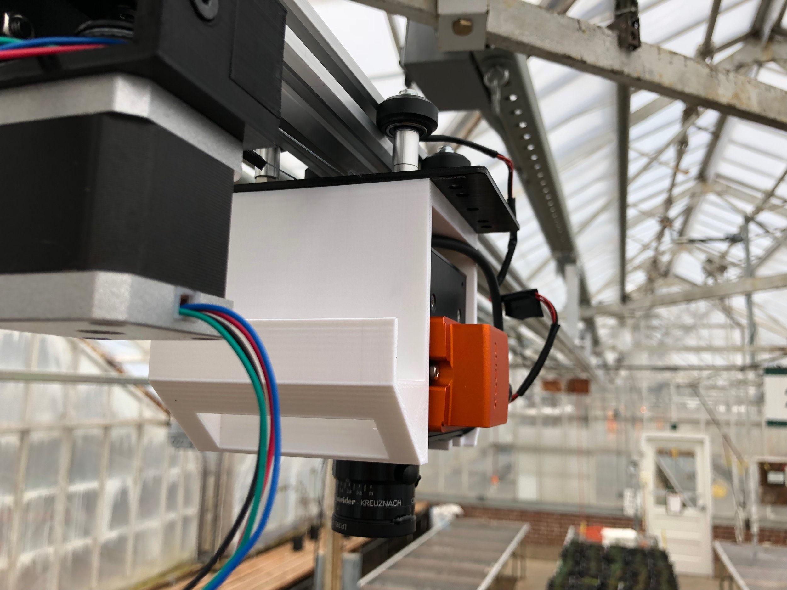
Design: The code was made modular so that it could be used on any microcontroller that could handle delays in the microsecond range and serial communication. The program also doesn’t make use of any libraries for the HyperRail to work. The Feather M0 LoRa is a great option for the HyperRail’s wireless communication upgrade because not only does it do serial communication and can handle microsecond delays but it can also do radio communication. Here is an image of the new microcontroller: 
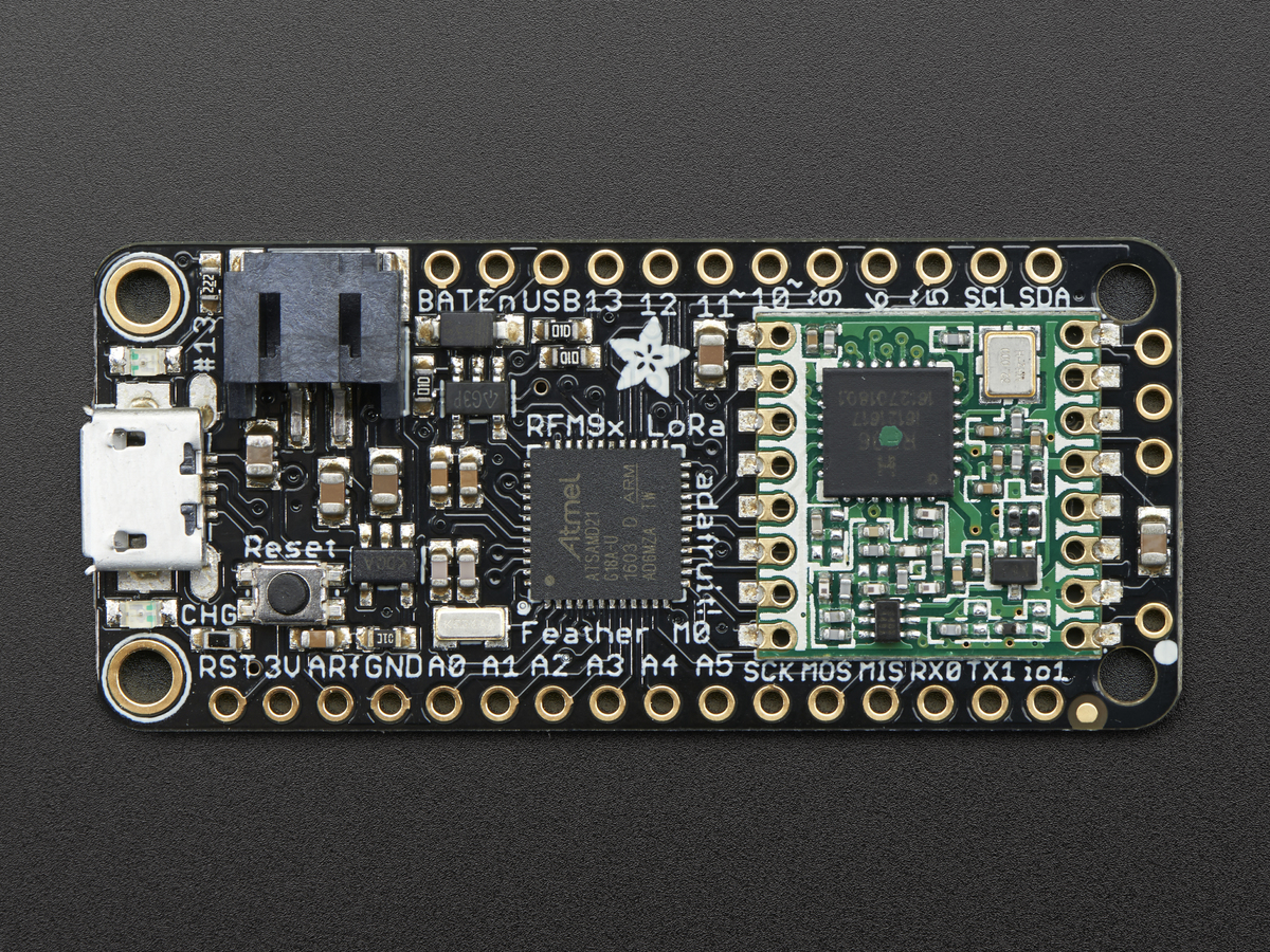

Feather M0 LoRaFeather M0 LoRa

Feather M0 LoRa

Here is the wiring diagram of this configuration:
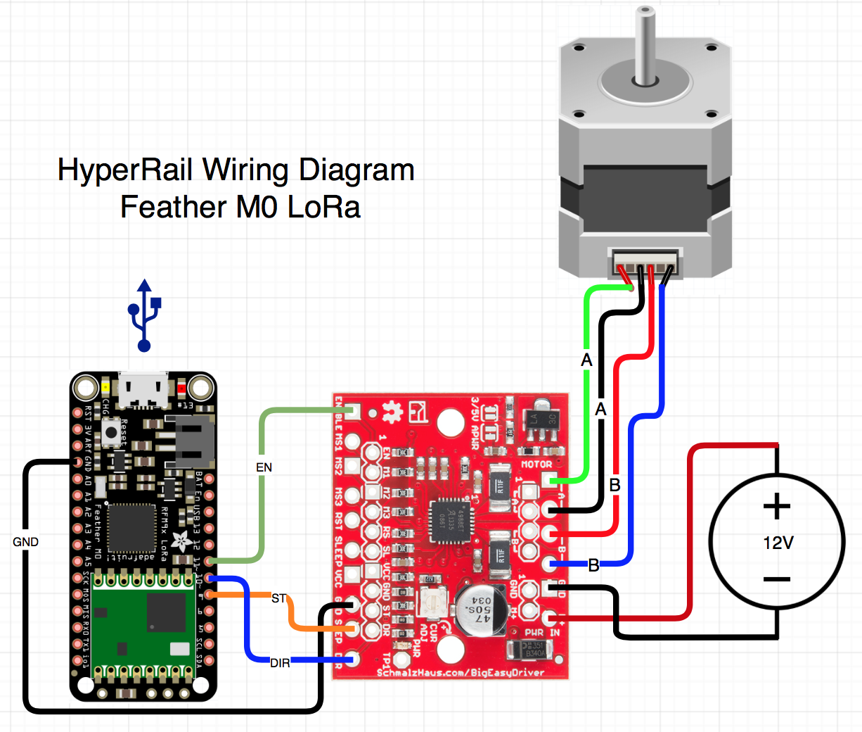

Wiring diagramWiring diagram

Wiring diagram

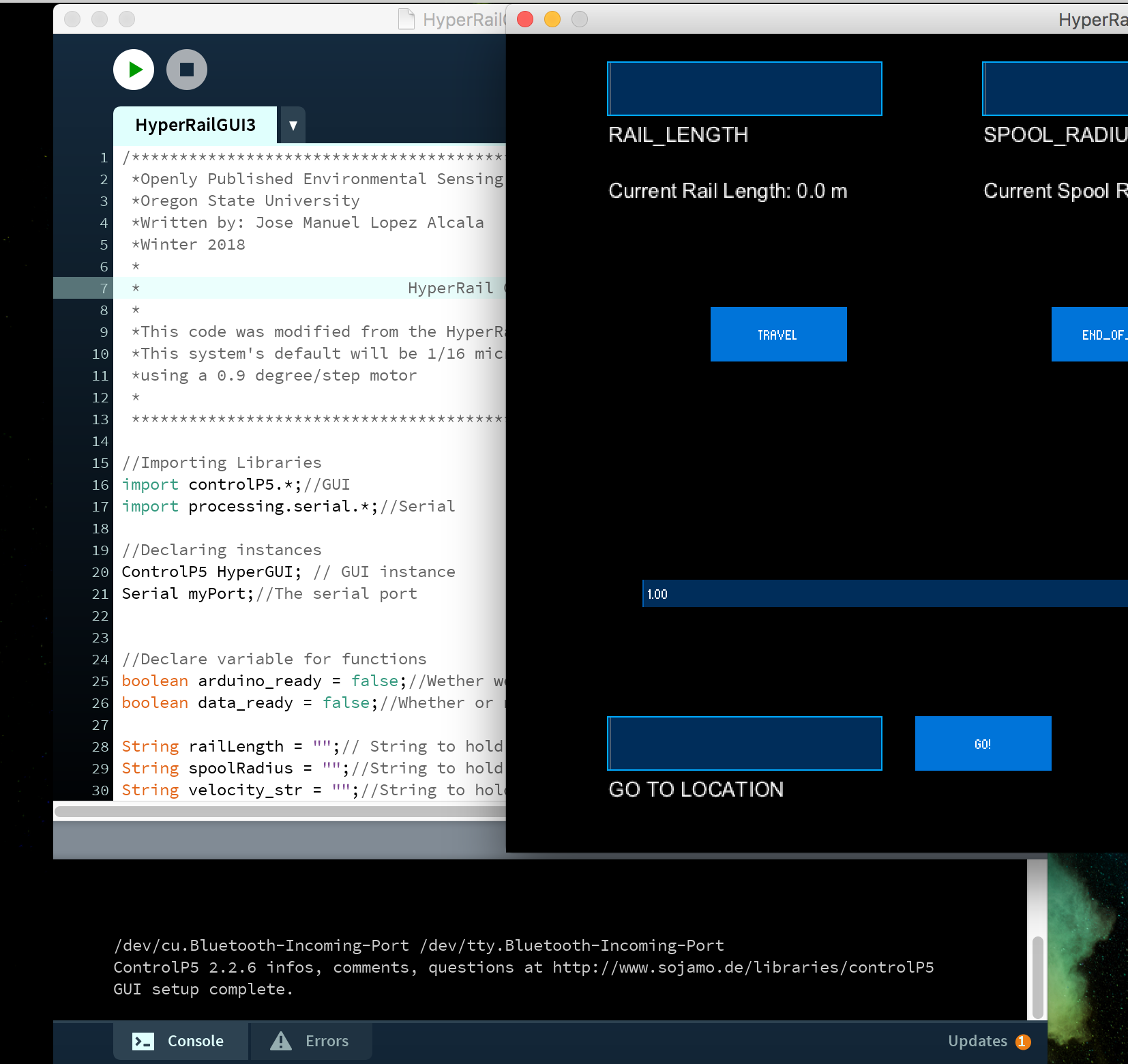
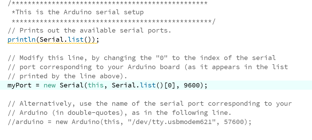
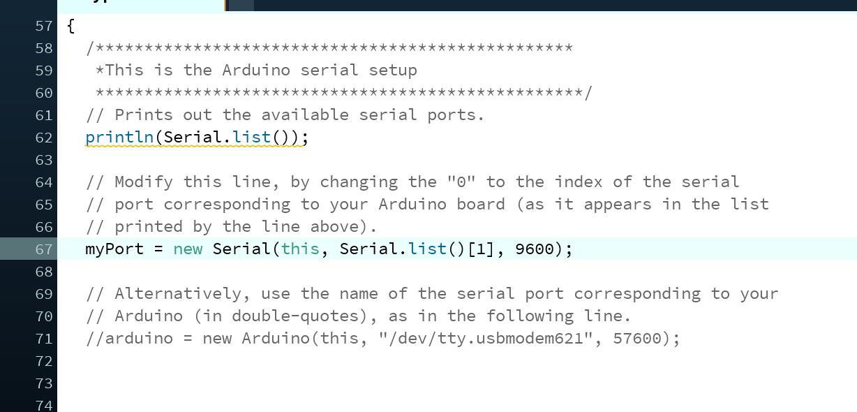
With some minor changes in the code, I was able to get the system working with the new microcontroller. Although the changes were minimal, it took some time to figure out what to change. One thing that wasn’t working was the serial communication, this is essential for the system to work. What was happening is that the Feather was outputting the serial prints way faster than the serial port would open, so I had to put in some checks for the serial port communication to be established first before any print statements were executed. Another thing I had to change was the pins used for the communication to the stepper motor driver.

Conclusion:

The upgrade to the new microcontroller went very well. I will now try to start sending commands to the microcontroller from another Feather and see how it responds. Here is a video covering the same points with a demo: 

HyperRail First Run

Abstract:
We took our first set of data of the pine seedlings using the HyperRail and hyperspectral camera. This post will be a summary of our setup for the data collection. 

Objective:
Inform about our setup of the HyperRail and give an overview of the data collection.

Setup
We are using 9 meters of V-Slot (aluminum extrusion), a gantry set (rolling base), all the 3D printed parts located here, this attachment, an Arduino UNO, and the Big Easy Driver. The code is also located in the code section of the main page of this project. 

Data collection Steps

1. Upload the sketch to the Arduino Uno and connect the computer to the microcontroller

2. Run Processing sketch and wait for the list of ports to appear on the bottom of the IDE of processing. It will say something like, “/dev/tty…” or “com#”


Screen Shot 2018-03-07 at 12.50.40 PM.pngScreen Shot 2018-03-07 at 12.50.40 PM.png

3. Change the port that the microcontroller is connected to in the code. Note that the ports are enumerated starting at the index of 0. An example would be, ” /dev/cu.Bluetooth-Incoming-Port /dev/tty.usbmodem621″ you would select port 1. Here is an example of the change of the port: 


Port located at index 0Port located at index 0

Port located at index 0


Port located at the index 1Port located at the index 1

Port located at the index 1

4.Run the code again and wait for the IDE to say “GUI setup complete” and a single “r”. The “r” is very important because that means that the microcontroller is communicating with the application and is ready to receive a command from the application; the are stands for ready. After this step, the HyperRail is ready to go. Now we need to setup the hyperspectral camera. 

5.Insert the camera in the case and then bolt in from behind or put a strap on the front. The bolts or strap are there for extra safety, not really neccesary, but it is still good to have. 


IMG_0286.jpgIMG_0286.jpg

6. Hook up the battery and turn on the camera.

7. Attach ethernet cable and start the data collection.


IMG_0305 2.jpgIMG_0305 2.jpg

8. Detach the ethernet cable. 

9. Star the HyperRail and wait for it to travel the rail. 

DEMO VIDEO:

Here is an example fo the data collected from the hyperspectral camera:


preliminary_data_spectralsignature.pngpreliminary_data_spectralsignature.png

Conclusions:
The HyperRail is working well. We will now move to improving the GUI for more functionality and upgrade the electronics for autonomous operation. This means that the sensor will in charge of moving the HyperRail’s carriage to where the sensor needs to be. We will be implementing the Feather microcontroller from Adafruit to do this because it has a LoRa radio to be able to communicate easily between feathers. I also need to run validation tests for the performance of the HyperRail to verify the precision of the movement of the carriage.