Most of the design for the rotating system is complete, but there are still some minor things to straighten out. One of the next things to design is the actual attachment to the pole that will be holding the whole system. This attachment has to be really strong because it will be holding the whole weight of the camera and rotating system. Here is the initial design of the base:
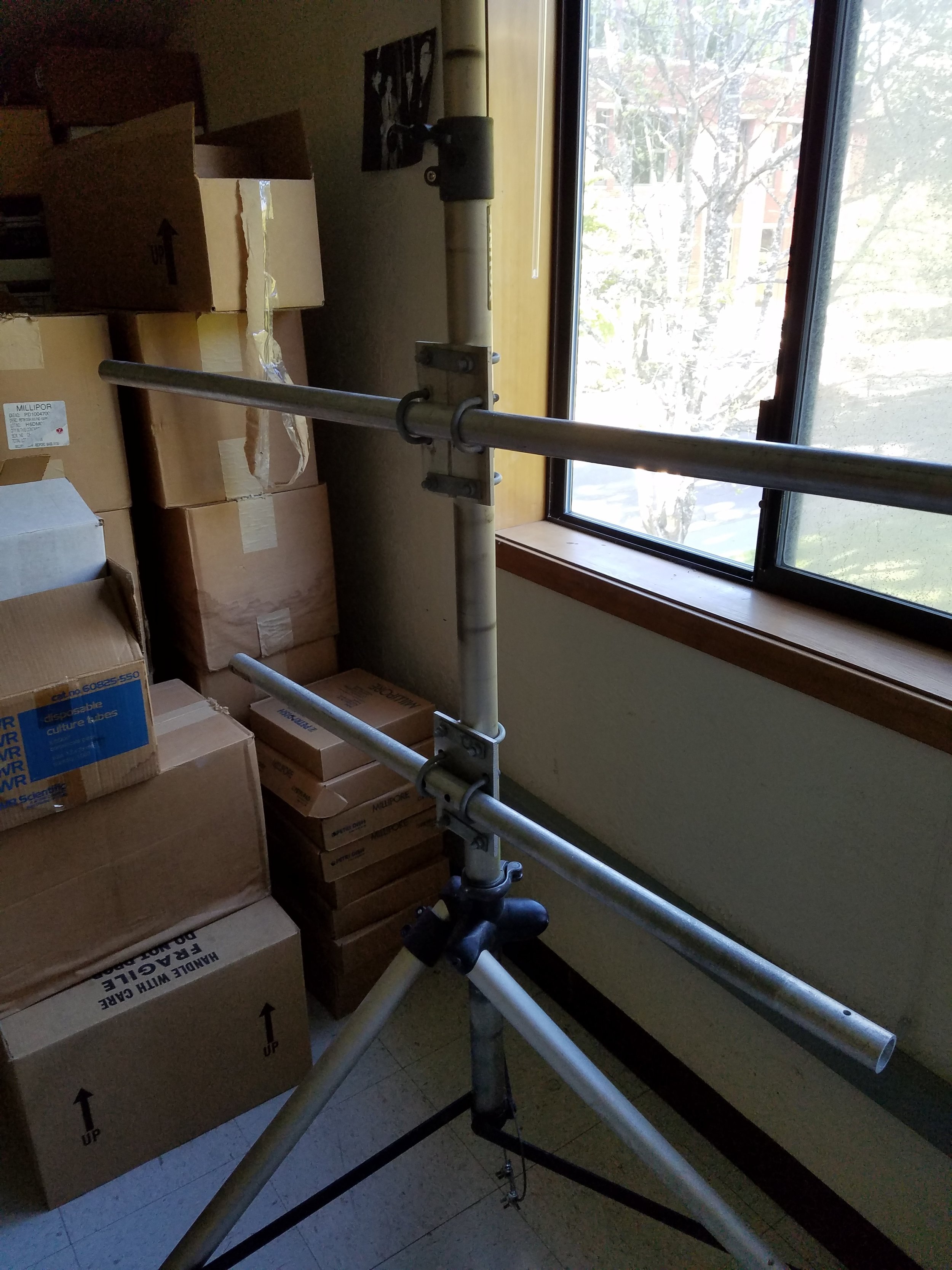
My initial idea is to have the attachment slide over the top of the pole and use some bolts as set screws to make sure that it will not move or fall off. The attachment has to also be connect to the motor housing. As of right now, I have four bolts coming from the motor housing into the base attach. I am trying to think about a way to get the nuts into the piece itselft, this way they are secure and will not fall out. I might just end up making a bigger holes on the bottom and use a socket to tighten them. Here is the the pole that we are using for this project.
Hyperspectral Camera Tripod
This week I will finish the design and print it. I will then proceed to mount the rotating system on it, and start testing the whole thing.
Here is a video for this week’s update. We now have the Arduino driving the motor. There are some things to work out with the 3D printed parts, but we are seeing the project come together.
As progress on the LoRa radios leads to integration into the Evaporometer Project, we take a closer look at some of the aspects of data transmission and providing portable power.
Sending and Printing Float Data:
The LoRa radios use packetized sending of 8 bit integers (corresponding to ACSII values) to relay integer and float data by first taking the integer value, changing each decimal value into the corresponding character (ASCII) value using iota(), and adding this info to the radio packet to be sent. On the receiving end, the data from the packet array is copied into a separate array, for our purposes its an array of 7 elements/bytes, and uses iota() to change it back into the correct integer value.
For float values to be sent, you need select a decimal value the suits your precision needs. For the Evaporometer we only decimal values to the ten thousandths place, and since our load cell will be taking measurements < 1000 grams I will need a maximum of 7 digits to store my data. The only difference I needed to make to send floats was to multiply the load cell’s measurement by 10,000 before setting it to the packet, and dividing by 10,000 in the receiver end. In order to print a float value, I also needed to include the precision value when using Serial.print() like so:
Serial.println(my_array,4);
Attaching the Battery Backpack:
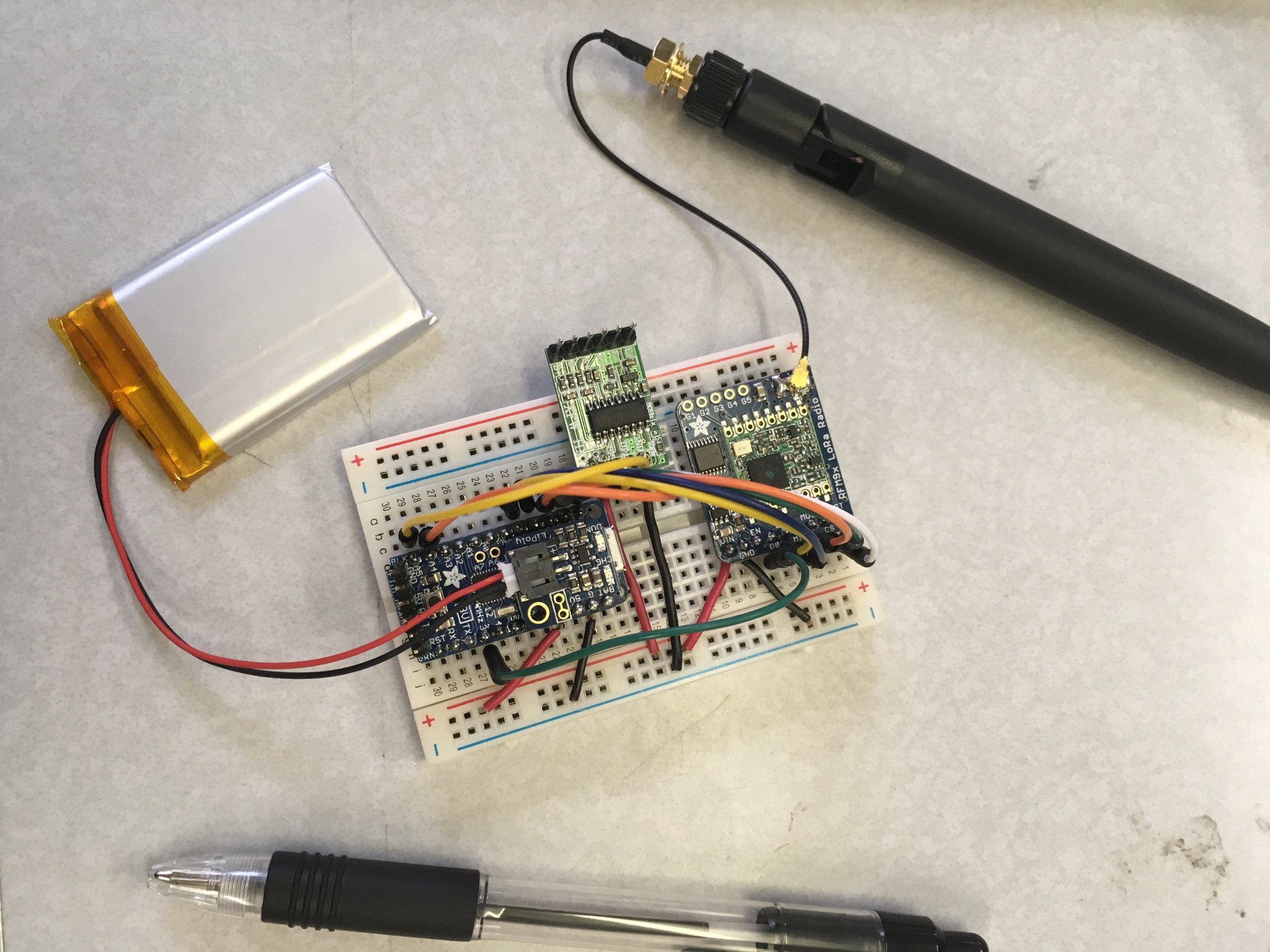
For our field test, it will necessary to rewire the LoRa chip, load cell, and pro trinket onto a smaller breadboard that can fit onto the housing designed for the Evaporometer. The Pro trinket is now powered off a portable LiPo battery. The micro-usb connector on the Pro trinket powers the device as well, and plugging the device into a wall outlet through the usb also recharges the LiPo battery. To improve signal strength the soldered in wire antenna was replaced with uff connector so that a larger antenna could be attached to the LoRa chip. The change in RSSI signal strength measured in the serial monitor reflected the changes I made to the antenna as well as the changes to the operating frequency (after we ramped up our new frequency to 915mHz).
Li-Po battery backpack connected to the ground, 5V, and bus pins on the Pro trinket
transmitter ready for housing; fitted with LiPo battery and uFL antenna (with pen to scale size)
– Marissa Kwon URSA Program Undergraduate Student Researcher
It’s been a while since we updated this blog on the drone build progress, but today the last part came in and the drone is officially flying! We still have to mount the RFID/GPS stack, so it’s not autonomous, but it’s flying very smoothly.
For the drone, we used:
CC3D Flight Controller
750kv 28-30 motors
30A SimonK ESCs
11″ propellors
5000mAh 4s 25c battery
Flysky T6 transmitter/receiver
S500 frame
Here is a short video showing part of its maiden flight:
Also, you may recall in the last drone update, we documented an issue where the Arduino Uno microcontroller would shut off mid-flight – this was because of a faulty UBEC that wasn’t supplying a steady 5v, forcing the Arduino’s internal regulator to work overtime and thus overheating. Replacing the UBEC solved the issue.
Now, we just have to program the autonomous navigation portion of the drone and mount the Arduino/RFID/GPS stack.
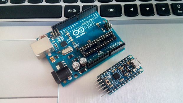
Converting from the Arduino Uno to the Adafruit Pro Trinket
As this project continues to develope, it is time to begin looking to add a more practical means of implementing these systems into the environment in a small and user-friendly package. The problem? The Arduino Uno is an excellent prototyping microcontroller, its easy to work with, has several built in functions with many pins ready to be used, however, this ease of use and functionality comes at the cost of a bulky, power hungry microcontroller that likely can do much more then you need it to. The solution? The Adafruit (3 Volt) Pro Trinket.
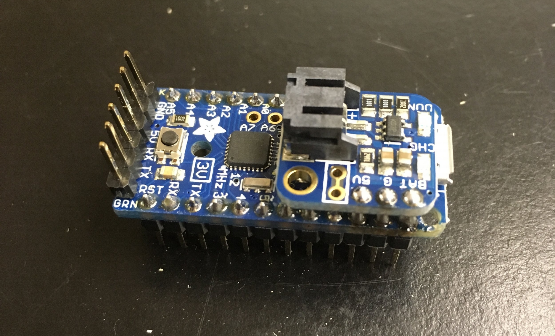
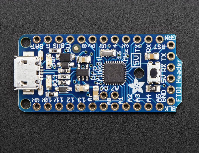
The Adafruit Pro trinket is a tiny microcontroller that packs a punch!
The New Adafruit Pro Trinket (3V) Micro controller being used for this project
Remapping Pin-outs
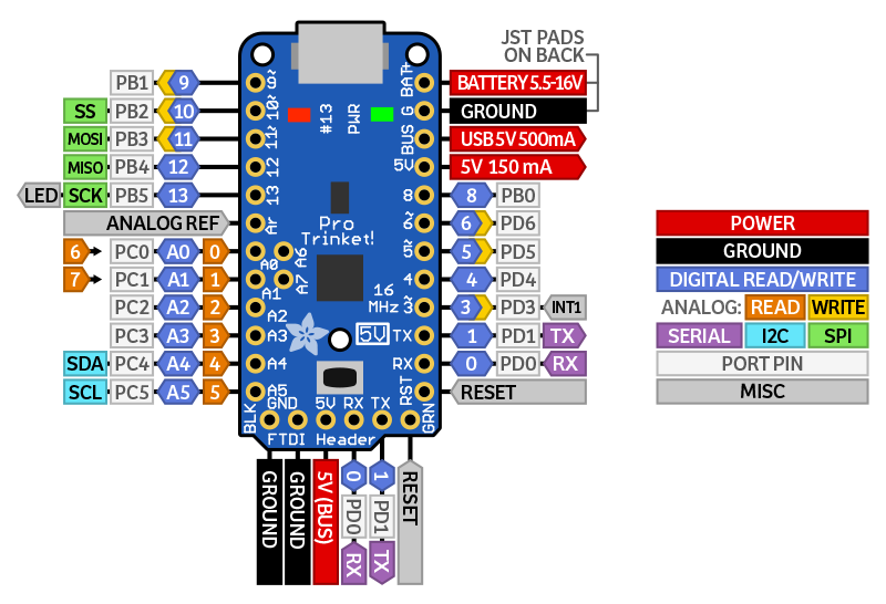
One of the biggest challenges with swapping the Pro Trinket for the Uno is the difference in board configurations and pin allocations. The blog post “Getting Started with the nRF08001 Bluetooth LE chip” lays out how the pins and wiring of the nRF08001 is set up for the Arduino uno. In this post we will be exploring how to do it for the Pro Trinket. Below is a diagram of the Pro Trinkets Pin outs as well as breakdown of the pin allocation.
Pin Schematic of the Adafruit Pro Trinket
RX – also known as Digital #0, this is the hardware serial input pin. This is used when programming with an FTDI cable but is available when using the native USB to program
TX – also known as Digital #1, this is the hardware serial output pin. This is used when programming with an FTDI cable but is available when using the native USB to program
Digital 3 – Also known as external interrupt #1. This pin can also be used as a PWM output pin using analogWrite()(This is the most significant difference between the Uno and the Pro-Trinket and requires manual changes to sketches in order to work)
Digital 4 – Nothing particularly special about this GPIO pin
Digital 5 – this pin can also be used as a PWM output pin using analogWrite()
Digital 6 – this pin can also be used as a PWM output pin using analogWrite()
Digital 8 – Nothing particularly special about this GPIO pin
Digital 9 – this pin can also be used as a PWM output pin using analogWrite() It’s also good for driving servos because its a high-speed PWM output
Digital 10 – this pin can also be used as a PWM output pin using analogWrite() It’s also good for driving servos because its a high-speed PWM output
Digital 11 – Also known as the SPI MOSI pin. this pin can also be used as a PWM output pin using analogWrite()
Digital 12 – Also known as the SPI MISO pin
Digital 13 – Also known as the SPI CLOCK pin. This is also connected to the red #13 LED!
Analog 0 – also known as Digital 14, this pin can be a digital I/O pin or an analog input pin
Analog 1 – also known as Digital 15, this pin can be a digital I/O pin or an analog input pin
Analog 2 – also known as Digital 16, this pin can be a digital I/O pin or an analog input pin
Analog 3 – also known as Digital 17, this pin can be a digital I/O pin or an analog input pin
Analog 4 – also known as Digital 18, this pin can be a digital I/O pin or an analog input pin. It’s also the I2C SDA pin
Analog 5 – also known as Digital 19, this pin can be a digital I/O pin or an analog input pin. It’s also the I2C SCL pin
Conclusions about the switch
The only changes you may have to consider when adapting Arduino sketches are:
Pins #2 and #7 are not available *
The onboard 3.3V or 5V regulator can provide 150mA output, not 800mA out, this is due to power saving functionality designed into the Pro Trinket, which is ideal for this project
You cannot plug shields directly into the Pro Trinket
There is no Serial-to-USB chip onboard. This is to keep the Pro Trinket small and inexpensive, you can use any FTDI cable to connect to the FTDI port for a Serial connection
The 3V Pro Trinket runs at 12MHz not 16MHz so its a bit slower, but with the advantage of significantly less power draw, extending battery life significantly
The bootloader on the Pro Trinket use 4KB of FLASH so the maximum sketch size is 28,672 bytes, more than enough space for almost all applications. The bootloader does not affect RAM usage.
And most importantly that all sketches that use pin 2 as the interrupt must be switched to pin 3.
Writing a script to bring it all together
This week I have also begin sketching the new data transmission protocol that will be used across the Internet of Ag project. After getting communication between the Pro Trinket and BLE module set up and the demo functioning it was time to start a new script from the ground up. This week I was able to begin drafting out the basic logic, and looking over example codes of the protocol and will contiune working on a sketch next week.
– Tom DeBell, Beginning Researcher Support Program researcher