For the last week, I worked on evaluating the potential of the ESP8266 as a WiFi communication device. It is a cheap WiFi module that is well-documented and thus suited to our project.
This is a guide that compiles and clarifies a few different sources into one to set up and ESP and Arduino Uno as a web server. If connected to the same network as the ESP, you can visit its IP address and see a customizable web page. This is a cheap and easy implementation that can be used for an Internet of Things project.
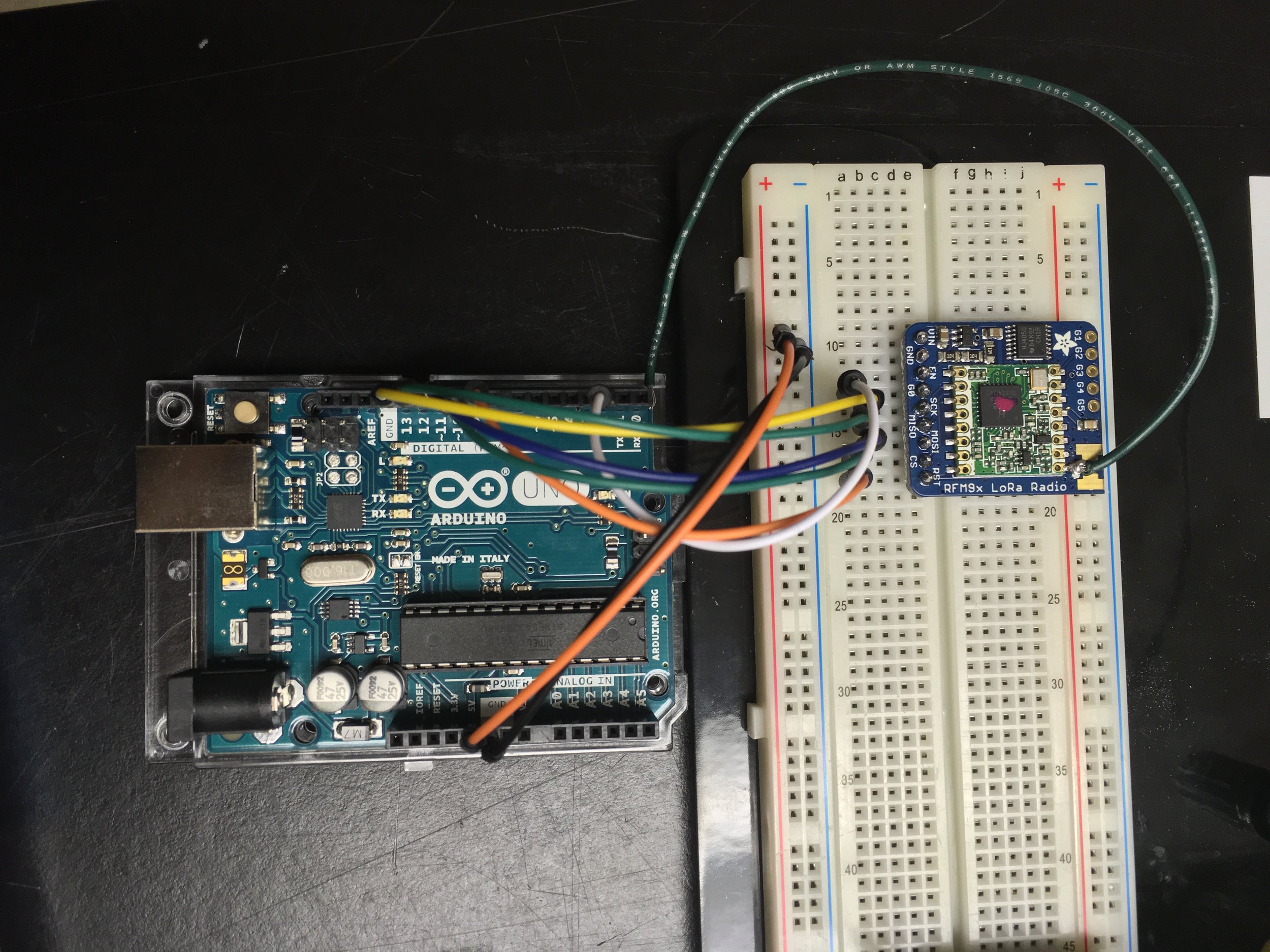
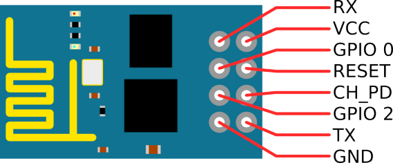
My starting point was an Arduino forum. First, I wired up the ESP and the Arduino, using this image as reference. Note: your board may say IO0 and IO2 rather than GPIO 0 and 2. Additionally, some boards may denote an EN pin instead of CH_PD pin.
Wiring:
I wired it up like this:
Arduino Pin ———- ESP Pin
2 ———————– TX
3 ———————– RX
GND ——————- GND
3.3V ——————– 3.3V (or 3V3)
3.3V ——————– CH_PD (or EN)
If you use the Arduino’s RX and TX pins directly, wire the ESP RX to the Arduino TX and the ESP TX to the Arduino RX. If you use these pins directly, you may need to disconnect them from the ESP when uploading your code, as these are used to upload code from the computer to the Arduino.
You will likely have to wire wrap, solder, or buy an ESP with headers added on to it, as it cannot be placed directly on the breadboard in its original form (this will connect the two rows of pins on the ESP to each other).
Code:
Once wired, upload the code available here. Note, this code has been borrowed and slightly modified (comments added and syntax error fixed) from allabouteee.com.
Information, original code, and guide video can be found at a post on allabouteee.com
Caveat: If using this code, note that lines 26-32 are commented out and can be removed. Additionally, lines 49 and 60 should be updated with variable name cipSend, rather than the incorrect cipsend.
AT-Command Information:
The setup in the code used several AT-commands to reset the ESP, set it up as a wireless access point, and get information from it. More detail about these can be found at itead’s AT command page. They can be used to update ESP firmware, change the SSID, add a password, etc.

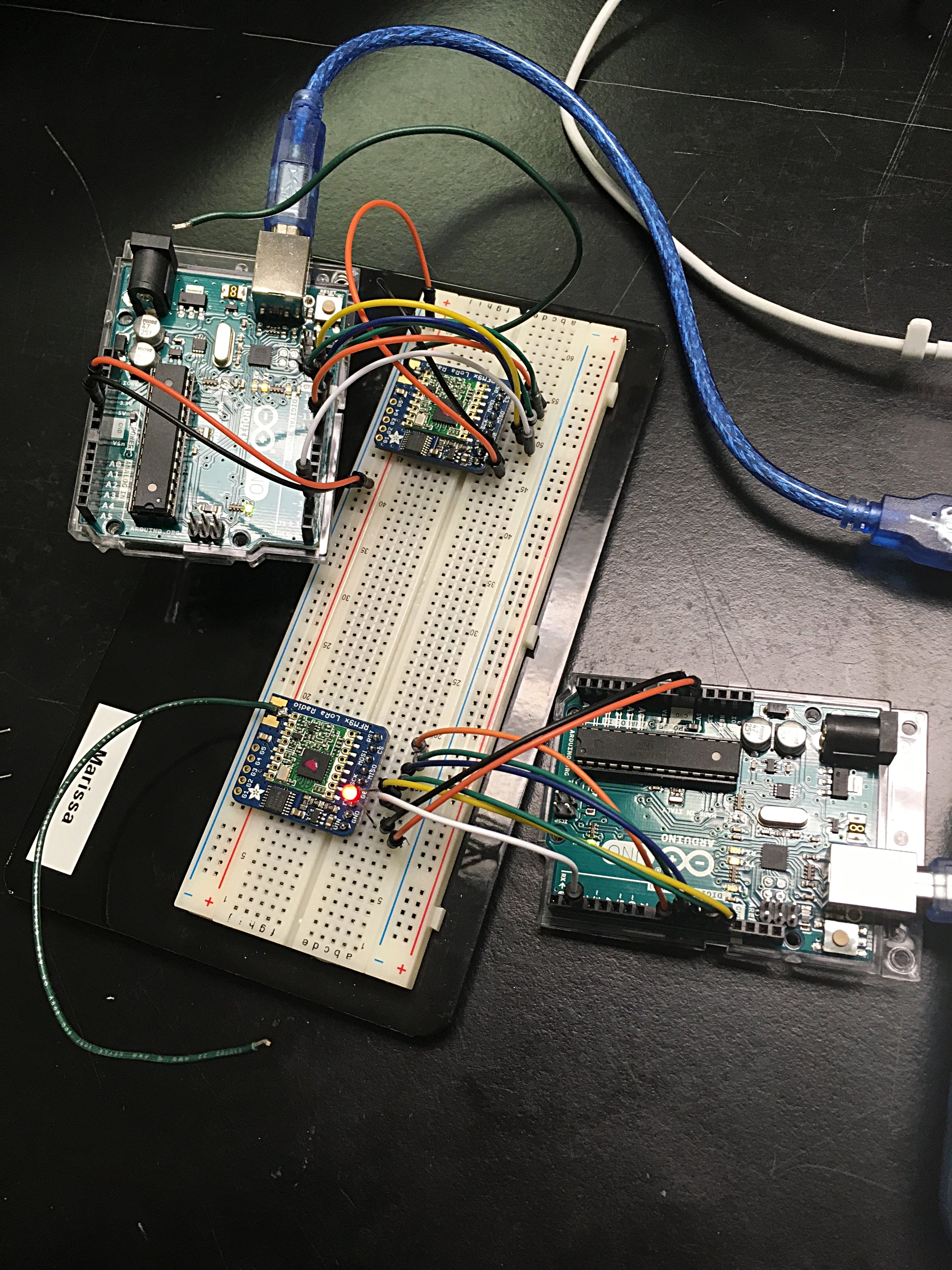
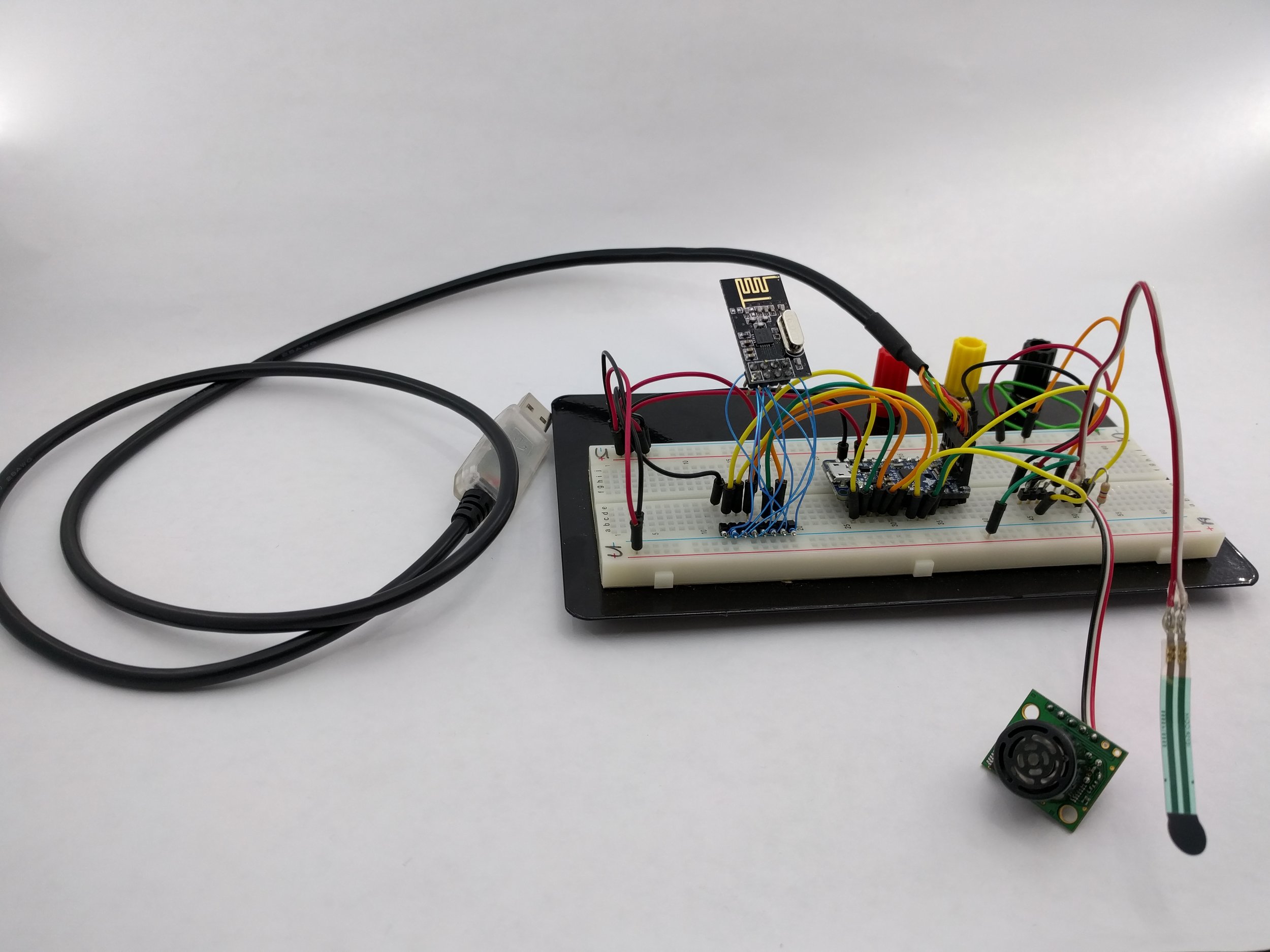
The ESP and Arduino wired up