What’s Up with the LoRa Devices

Abstract:

This post describes all progress up to this point and the integration of LoRa communication into the currently in progress Evaporometer project.

Our Progress:

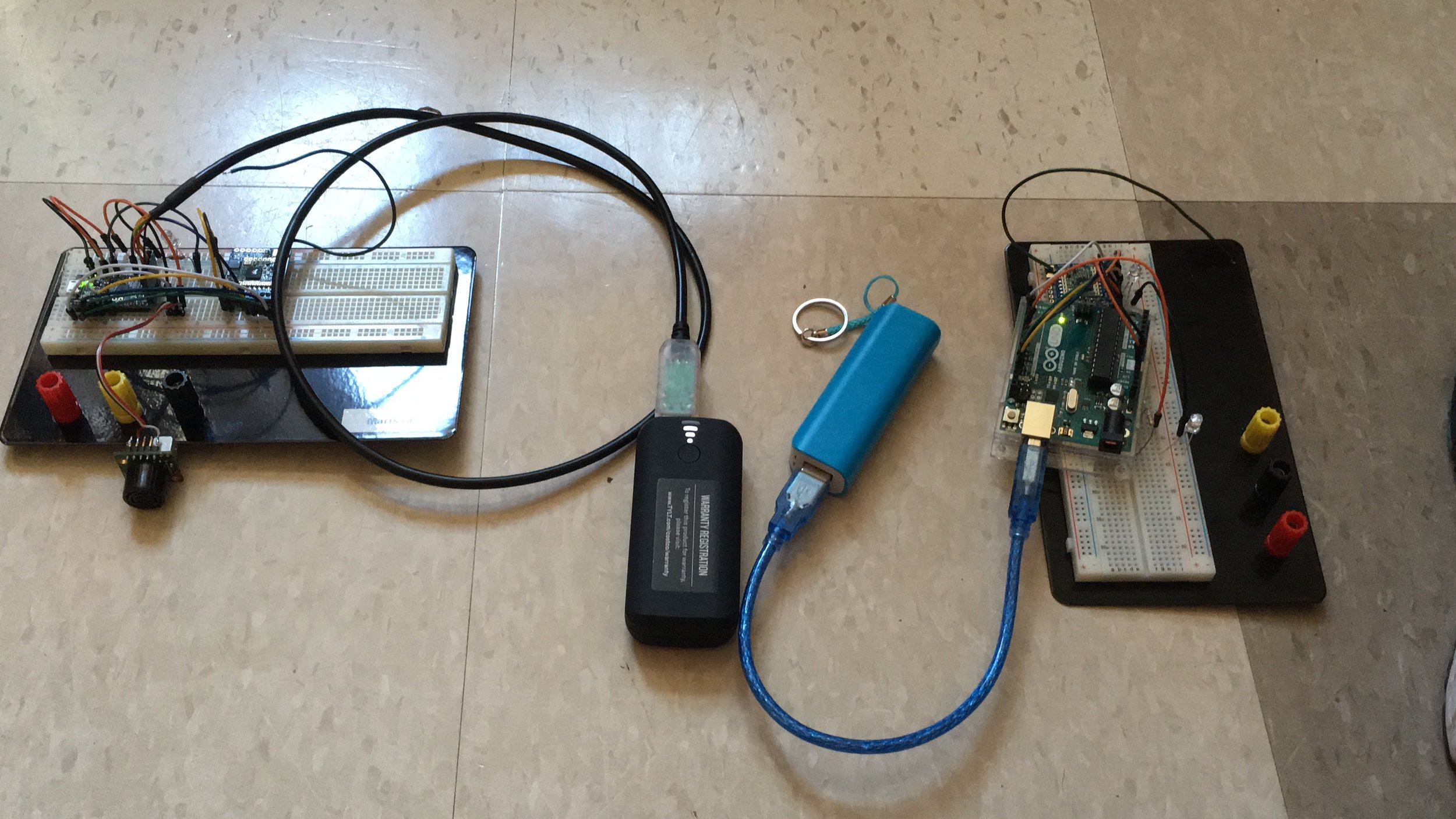
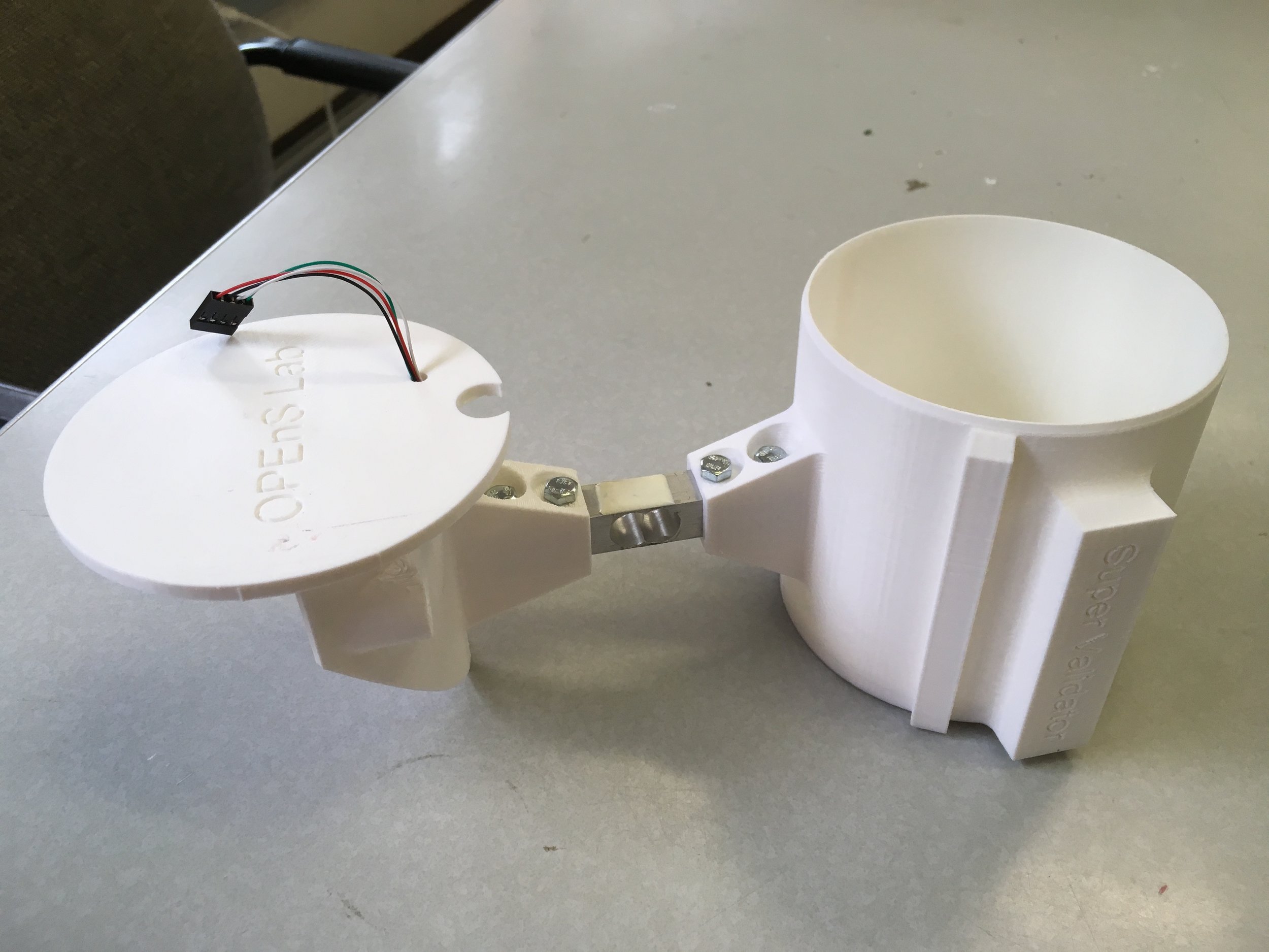
In the past few weeks, I’ve been working with another student named Manuel to apply the LoRa devices to a rain catchment device designed to measure evaporation.  Below is a picture of the strain gauge rain catchment system he built for the project.  The LoRa device can be placed on the platform where a load cell can be hooked up to our LoRa system to measure and transmit data to our LoRa receiver and to an offsite server.  


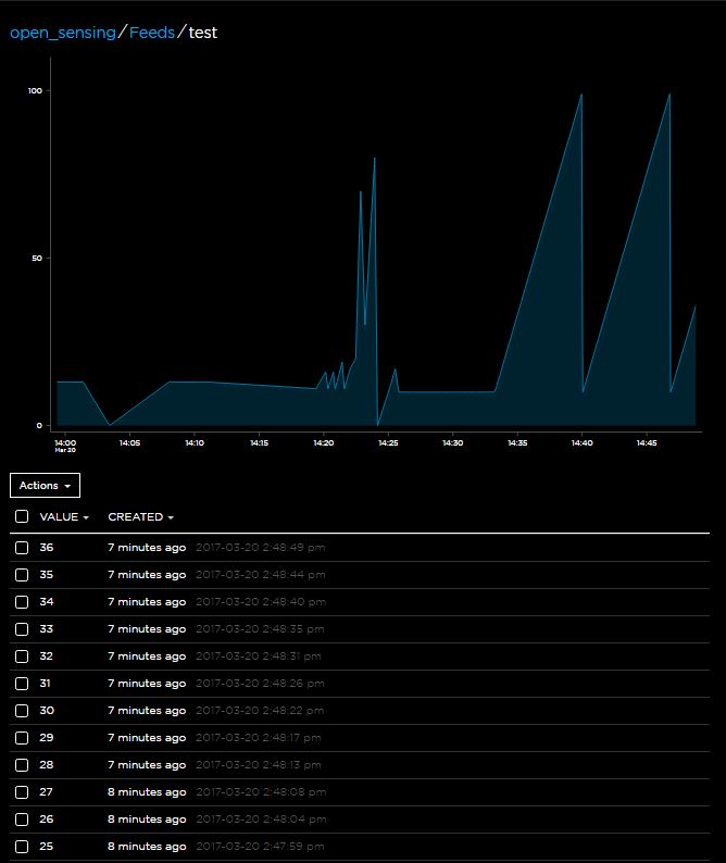
Since the LoRa device will need to transfer data as precisely as our load cell can measure, the code will need to be adjusted to accommodate integer and float values with adjustable decimal precision.  I have made the proper updates to the code and will post more details on that in the future.

What’s Next:

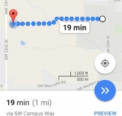
We are moving quickly towards field testing these LoRa devices with the Evaporometer but there are a few changes that still need to be made.  The LoRa transmitters, which will be out in the field, will need a weatherproof housing and a portable power source.  Also our current transmission frequency is not suitable for a lot of ongoing communication, so our LoRa breakouts will also need to be replaced new ones that can transmit at a higher 915 mHz frequency.   

Marissa Kwon Undergraduate Student Researcher

Coding with the nRF08001 Chip and Other Evils

Testing Aftermath

After concluding testing on basic functionality earlier this week with positive results , it was time to dig into the real work… developing a protocol that would allow this Bluetooth LE breakout board to be used to transmit sensor data in a convenient and uniform way across the “Internet Of Agriculture” project . In addition, a second nRF08001 module was set up, and experimenting with two modules began.

Phase one – understanding the “out of the box” software

Before trying to construct an entire comprehensive script from scratch,  I thought it would be worth my time to familiarize myself with what others have done in some of the demo codes I explored here on Github.  

The code currently running on the two Arduinos (found here) has be modified slightly by myself but in general the  framework is done using universal asynchronous receiver/transmitter (UART)  protocol , where the data format and transmission speeds are configurable. The electric signaling levels and methods (such as differential signaling, etc.) are handled by a driver circuit external to the UART, in our case an Ardiuno uno, and eventually something as small as an Adafruit Pro Trinket . In other words, the UART takes one channel to transmit data and one to receive it.  

UART Sketch in detail (Part 1)

Initialization

Like most Arduino sketches the first step is to initialize the device in question (in our case the Arduino or Pro Trinket), and prepare the hardware for the data its about to send and receive. You’ll need to include the header files and define the pins used. Since we’re using hardware SPI, the CLK/MOSI and MISO pins are fixed (see wiring scheme in “Getting Started with the nFR08001” blog). 

the RDY pin is the only pin that must be an interrupt pin. We’ll use 2, most Arduino’s can use 2 or 3.

Then create the Adafruit_BLE_UART object at the top as shown below. 


These few lines of code are enough to get the Arduino oriented to the hardware and are the first steps to begin further use of the BLE module.

Unfortunately due to time constraints and hardware not cooperating, this is as far as we got this week. However, further exploration will continue.    

– Tom DeBell, Beginning Researcher Support Program researcher

ESP 8266 and IFTTT

By: Alex Grejuc

Background:

I have been working on connecting to IFTTT using the ESP. IFTTT is a platform that makes it easy to connect different web apps and services to create applets or recipes. They work in an If this, then that (that is where the letters IFTTT come from) format. For example, if I like a video on YouTube, save its name and link to a list on Evernote.

IFTTT has a service called Maker that allows a user to send a web request to their Maker service which can then trigger an action. I used this feature to create an applet, which, when triggered by the ESP will send data to a Google Drive spreadsheet.

Process:

This will be wired the same way as all my previous Arduino and ESP guides. Most of the code is fairly similar and it is explained there as well. The wiring is here and the general info about sending GET requests is here.

The first step is to create an IFTTT account and then create an applet (this link answers many of the questions about applets) using Maker.

After creating an applet, go into settings on the Maker page.


settingssettings

Then, copy your personal URL and go to that page.


On this page, you can see the information for sending HTTP requests and the full link that can be used in a GET request. The code will show how to add data values which can be sent over as query parameters in the request.


Once this is all set up, you have the necessary information to send data to the web using IFTTT and your ESP.

Next, download the code, add your credentials, and then upload it to the Arduino.

This guide may be helpful, it is how I got my start. However, like many of the guides, this uses the ESPWifi library which I did not use.

More Testing with the nRF08001 Bluetooth LE

Note: The nRF8001 sends out packets of data, 20 bytes at time. Keep this in mind if you want to send a lot of data it will be packetized into chunks of 20. You can of course send less than 20 bytes.

Exploring Mobile Interface

After initial setup and software tests, I was able to explore the Adafruit developer smart phone application found in the android market, “BlueFruit LE”. (APK file linked here

Much like Serial you can use the .write and .print functions allow us to send data out to the connected device:

Features included in Bluefruit LE App


Home screen of the "Bluefruit LE" smartphone applicationHome screen of the "Bluefruit LE" smartphone application

Home screen of the “Bluefruit LE” smartphone application


Display after connection with Bluetooth moduleDisplay after connection with Bluetooth module

Display after connection with Bluetooth module

Info

Displays MAC address and other relevant Device Information


Screenshot_20170412-101741.pngScreenshot_20170412-101741.png


UART


Screenshot showing a message being transmitted to the Arduino from my smartphone Screenshot showing a message being transmitted to the Arduino from my smartphone 

Screenshot showing a message being transmitted to the Arduino from my smartphone 

The “UART” function allows a basic text message interface from smartphone to the Arduino Series monitor. However, after testing it was apparent that although the application allows infinite characters of transmission, the messages are broken apart into 20 character fragments due to the data transmitting capabilities of the bluetooth chip.


Snip showing successful reception of the message from my smartphone to the Arduino seriel monitorSnip showing successful reception of the message from my smartphone to the Arduino seriel monitor

Snip showing successful reception of the message from my smartphone to the Arduino seriel monitor


Pin I/O

The Pin I/O section of the mobile phone application allows the user to control input and output of pins (both analog and digital) on Arduino shield. However, this particular function required significant code modification in order to allow functionality on Android enabled devices. Once the code is finalized it will be published and linked here. In order to display this faciniating functionality a small demo was contructed in order to deminstate the smart phone interfaces capabilities. 


With just a slide of my finger I am able to modify the signal strength being admitted from the Arduino With just a slide of my finger I am able to modify the signal strength being admitted from the Arduino 

With just a slide of my finger I am able to modify the signal strength being admitted from the Arduino 


The Blue LED is only lightly illuminated due to low PWM signal as specified by the photo on the left The Blue LED is only lightly illuminated due to low PWM signal as specified by the photo on the left 

The Blue LED is only lightly illuminated due to low PWM signal as specified by the photo on the left 


The PWM slider was moved all the way to right to allow for maximum signal strengthThe PWM slider was moved all the way to right to allow for maximum signal strength

The PWM slider was moved all the way to right to allow for maximum signal strength


The increased signal strength as shown on the left caused the LED to shine brightlyThe increased signal strength as shown on the left caused the LED to shine brightly

The increased signal strength as shown on the left caused the LED to shine brightly

This section of the Bluefruit LE application appears to be very useful, unstable and will require further explanation.

Controller

Streams sensor data from smart phone sensors (Quaternion (6-axis accelerometer), Accelerometer, Gyro, Magnetometer, Location)

Beacon

Puts smartphone in a state to receive pop-up text messages from serial monitor up to 20 characters  


Snip from the Arduino Serial Monitor during transmission testingSnip from the Arduino Serial Monitor during transmission testing

Snip from the Arduino Serial Monitor during transmission testing


Screenshot of the recived message from the Ardiuno Screenshot of the recived message from the Ardiuno 

Screenshot of the recived message from the Ardiuno 


          Messages are restricted to only 20 characters           Messages are restricted to only 20 characters 

          Messages are restricted to only 20 characters 

Neopixel

Needs further exploration.


Conclusions

**Initial testing of connectivity shows an approximate range of 20 feet for reliable signal strength.**

After initial testing it would appear that  the Pin I/O will have the most practical capabilities and research of its functionality will continue. 


– Tom DeBell, Beginning Researcher Support Program researcher

Getting Started with the nRF08001 Bluetooth LE chip


Initial setup for this project began early this week starting with soldering header pins onto the nRF08001 Bluetooth LE (Low Energy) breakout board so that a physical connection could be made with an Arduino Uno module to begin testing. A valuable resource that helped getting started can be found at adafruit.

The wiring of the Bluetooth board to the arduino was done as follows. 

Wiring Schematic


Wiring Schematic via Adafruit Wiring Schematic via Adafruit 

Wiring Schematic via Adafruit 


Wiring completed on April 5th to begin testingWiring completed on April 5th to begin testing

Wiring completed on April 5th to begin testing

  • VIN connects to the Arduino 5V pin (Red Wire)
  • GND connects to Arduino ground (Black Wire)
  • SCK connects to SPI clock.  (Blue Wire)
    On Arduino Uno/Duemilanove/328-based, thats Digital 13
    On Mega’s, its Digital 52 and on
    Leonardo/Micro its ICSP-3 (See SPI Connections for more details)
  • MISO connects to SPI MISO. (Yellow Wire)
    On Arduino Uno/Duemilanove/328-based, thats Digital 12
    On Mega’s, its Digital 50 and on
    Leonardo/Micro its ICSP-1 (See SPI Connections for more details)
  • MOSI connects to SPI MOSI. (Teal Wire)
    On Arduino Uno/Duemilanove/328-based, thats Digital 11
    On Mega’s, its Digital 51 and on
    Leonardo/Micro its ICSP-4 (See SPI Connections for more details)
  • REQ connects to our SPI Chip Select pin. We’ll be using Digital 10 but you can later change this to any pin. (Grey Wire)
  • RST connects to Digital 9 – this is for resetting the board when we start up, you can later change this to any pin. (Orange Wire)
  • RDY is the interrupt out from the nRF8001, we’ll connect to Digital 2 but be aware that if you want to change it, it must connect to an interrupt capable pin (see this Arduino page for which pins are interrupt-capable. Digital 2 is OK on Uno/Leonardo/Micro/Mega/etc.) (White Wire)
  • Note: Wire colors refer to first wiring diegram

Initial Testing

After wiring was completed testing of bluetooth transmissions and functionality began with positive initial results. By running a sample arduino code found on GitHub we were able to communicate to the arduino via the “Bluefruit LE” android application and likewise was able to transmit data from the command line of the arduino workspace directly to a smart phone via the bluetooth module.  Further Testing will contiuno next week.


Snip from the Arduino Serial Monitor during testingSnip from the Arduino Serial Monitor during testing

Snip from the Arduino Serial Monitor during testing

– Tom DeBell, Beginning Researcher Support Program researcher

Testing the range of LoRa radio breakouts

Abstract:

Today I confirmed that the range of the LoRa devices is at least 1-2 km; the documented range on Adafruit’s website is 2km line of sight in an open area.  I took a walk and brought along one LoRa radio to the far west side of campus.  

Procedure:

Code on the Pro Trinket and the Arduino has been modified to send updated sensor values to and from the transmitter as packets of data.  I the receiver along on my walk and waited for the LED to stop blinking indicating that nothing was being transmitted.  In the video below, the red LED on both radio units lights up if the sensor hooked up to the transmitter sends a value below 36 cm to the receiver:  


LoRa_rangeLoRa_range

Results:

About 1.6 km (a mile) of open space was between the receiver and the transmitter before I reached some tall trees and the connection began to cut out.


What’s Next:

Now that I have the two radios constantly sending signals back and forth, my next job will be implementing a timer to limit the sending of sensor values to once every second and eventually use the LoRa radios into transmit data from a rain catchment  device.

 Marissa Kwon Undergraduate Student Researcher

Adafruit IO data logging update

By: Alex Grejuc

I have been working on using an Arduino and an ESP8266 wifi module to log data on an online platform for the past few weeks and after many hurdles, I have something that works reliably.

The general progress can be seen in the previous blog posts, so I will not discuss that.

Background:

This code hinges around sending HTTP GET requests. GET is an HTTP method that “asks” for a resource (a web page) from a server. In this case, we are requesting to send data to the IO platform. A GET request follows the general format:

GET HTTP/1.1

Host: <host>

Connection: close\r\n\ (connection can also be kept alive with keep-alive)

When sending these over the ESP, \r\n (carriage return and newline characters) must be appended to each line (the last line has an extra \r\n). Without them, the command may not be properly understood by the server.

Once this command is sent, the server will respond by returning html. This is essentially how an internet browser functions: a URL is entered, the browser receives html from a server, and then displays the html. In this case, however, the response is going to the ESP, which will display “+IPD” (which indicates the ESP has received data) to the serial monitor and then the HTTP code and some html. My information of networking and HTTP is very limited, so much more information can be found online. A resource I skimmed can be found here.

Process:

First, I created an Adafruit IO account and familiarized myself with the platform. Adafruit IO is a platform for the internet of things that makes it easy to record and view data. They have a lot of documentation, tutorials, and support, so it is a good choice. Note that their recommended route for using the ESP8266 involves the Huzzah breakout and uploads code directly to the ESP8266. This was not quite what we wanted to do, so I worked on interfacing with the ESP through the Arduino by sending AT commands.

Next, wire up the ESP and Arduino and get familiar with the ESP and its AT commands. All of this information can be found in this previous blog post. The code there is for a different purpose, so that can be ignored.

After that, upload this code and fill in your own WiFi and Adafruit credentials.

This should be enough to get a bare bones method of logging data up and running.

Extra Resources:

Additionally, here are a couple of posts and websites that helped me troubleshoot and understand what was going on:

  • Arduino forum on an ESP GET request issue
  • The Adafruit page that explains how to send and receive data using HTTP requests
  • A post with more detail on some AT commands
  • A video that goes over the process, which helped me break through my issues


Adafruit_data

Progress with LoRa Transmitter/Receiver

Abstract:

In this blog post we go over how to we assembled the LoRa transmitter and receiver.  We include instructions on how to set up the Arduino IDE as well as the code for our test devices.


Update:&nbsp;Transmitter (left) and Receiver (right) on separate breadboards connected to portable 5V power sourcesUpdate:&nbsp;Transmitter (left) and Receiver (right) on separate breadboards connected to portable 5V power sources

Update: Transmitter (left) and Receiver (right) on separate breadboards connected to portable 5V power sources

Materials:

These are the components connected to now separate transmitter/receiver (pictured above): 

Transmitter:

– Matbotix 1220 sonar sensor

– RFM9X LoRa Radio

– Adafruit Pro Trinket (3V Logic) w/ FTDI cable connector

– Red LED

– 51 ohm resistor

Receiver:

– RFM9X LoRa Radio

– Arduino UNO (5V out) w/ macro USB cable connector

– 81 ohm resistor

– Red LED 

– White LED

The transmitter and receiver have been placed on separate breadboards in order to test the range on the LoRa chips.  Code on both the transmitter and receiver sketches has been rewritten to send and receive the data values measured by the MB1220.  Other changes include the replacement of the Arduino Uno development board with the smaller 3V Adafruit Protrinket.  If you haven’t already, you will need to set up your Arduino IDE so that it recognizes Adafruit’s development boards when plugged into the USB port using an FTDI cable.  

SETTING UP THE ARDUINO IDE: You will need to go into Arduino’s Preferences, paste the Adafruit Board Support Package URL into the space next to “Additional Board Manager URLS”, click OK, then go into the Tools tab and select the “Boards Manager” found in “Boards:”.  Filter your search by choosing “Contributed” from the dropdown menu and typing “Adafruit AVR” in the search bar.  Then install the package “Adafruit AVR Boards”.  Once installed, you can upload your Arduino sketches to the Pro Trinket by selecting “Pro Trinket3V/12MHz (FTDI)” from the Boards dropdown menu.

The Pro Trinket uses the Atmega328P chip – the same core chip as our Arduino UNO – making it easy to switch between the two.  When transitioning to the Pro Trinket I realized it lacked pins #2 and #7 as well as the level shifting featured on the UNO (5V input on the Pro Trinket will have to be reduced to 3.3V to prevent damage to the board). To accommodate the Pro Trinket, I replaced interrupt Pin#2 for Pin#3 and digital write Pin#7 for Pin#6 and applied these changes to the UNO so the transmitter and receiver code can be used for either board.   Here are the updated versions of the transmitter and receiver code.

I have provided links to more information about the Pro Trinket’s limitations compared to the UNO and step by step instructions for installing the Adafruit AVR package.

 Marissa Kwon Undergraduate Student Researcher

Logging data on Adafruit IO

By: Alex Grejuc

Today I finally succeeded in getting “data” (arbitrary numbers that I either hardcoded or looped through) from the Arduino through the ESP and to Adafruit IO.

I troubleshooted my bad requests by sending in AT commands manually through the Arduino serial monitor. After digging around on the internet, I found that the Arduino serial monitor does not recognize the \r and \n (carriage return and newline) escape sequences, so I sent each line of the GET request in line-by-line, and it worked.

This was manifesting itself in my code too because my character counts were off (the ESP AT command requires the length of the argument you are going to send it and will not work properly if it is off). After troubleshooting, I found the “correct” character count for my requests and I was able to receive a proper response from an Adafruit test page.

After this, I looked into sending a GET request to the IO platform with data. I was able to get this working as well and published some test data to an Adafruit “feed.”

I plan on cleaning up the code by writing some functions to make it more readable and easier to use as well as updating my comments now that I have a better understanding of the process. Once I do this, I will publish the code along with some of the resources that helped me along the way.

Here is a screenshot of some of the data on the Adafruit IO website.


Current Progress on ESP8266 data logging

By: Alex Grejuc

After learning to interface with the ESP through the Arduino and hosting the basic web server, I started working on actually using the ESP to get data from the Arduino and log it on an online internet of things platform.

I started out by looking into a few different IOT platforms: Adafruit IO, IFTTT, and Xively. Of the three, Adafruit seemed like the best option because it was free and had tutorials for integrating a custom Adafruit ESP breakout board.

I started out working from an Adafruit tutorial. to simply learn how to connect to the Adafruit server and receive a response. However, this tutorial was intended for the Adafruit custom board and uploaded the code directly to the ESP8266 with an Adafruit library. I spent time “translating” their code into AT-commands by determining what they were doing, finding an AT command for it, learning how it works, and then sending it over.

Connecting to a network and starting a TCP connection with the Adafruit server was easy to do, however, the HTTP GET request has provided plenty of trouble.

Initially, after sending the request the ESP replied with “Send OK” but did not receive or print the response to the Arduino serial monitor. After trying many things, I thought there might be an issue with the Adafruit server I was attempting to get data from.

I then decided to try sending a GET request to a different server in case that was indeed the issue, so I set up an IFTTT applet. It would send my phone a text message when a request was sent in, based it off of a tutorial someone made for interacting with IFTTT using the ESP. This seemed like a good approach because I could see if the GET request worked without even reading any response in with the ESP, in case that was the issue.

This also did not work, so Dr. Udell and I came to the conclusion that the Oregon State wireless network might prevent the ESP from receiving the response somehow. This turned out to be true: after connecting to two different networks on campus (an OSU robotics one and a personal cellphone hot spot), the ESP got a response from the server.

Unfortunately, the response is a “Bad Request Error 400” response that I have been troubleshooting since. It seems to be a common issue based on forums, but no clear solutions have been found. I hope to provide a more robust update with code, links, and information once I can successfully get the request to work.