
Peristaltic 12V dosing pumps are cheap and provide a large enough volumetric flow rate for our needs. Unfortunately there is not much information available on the type we are using. This post will discuss the method we are using to test the reliability and consistency of these pumps over a period of two hours. It is the first of several tests we will be conducting on different components of our water sampler.
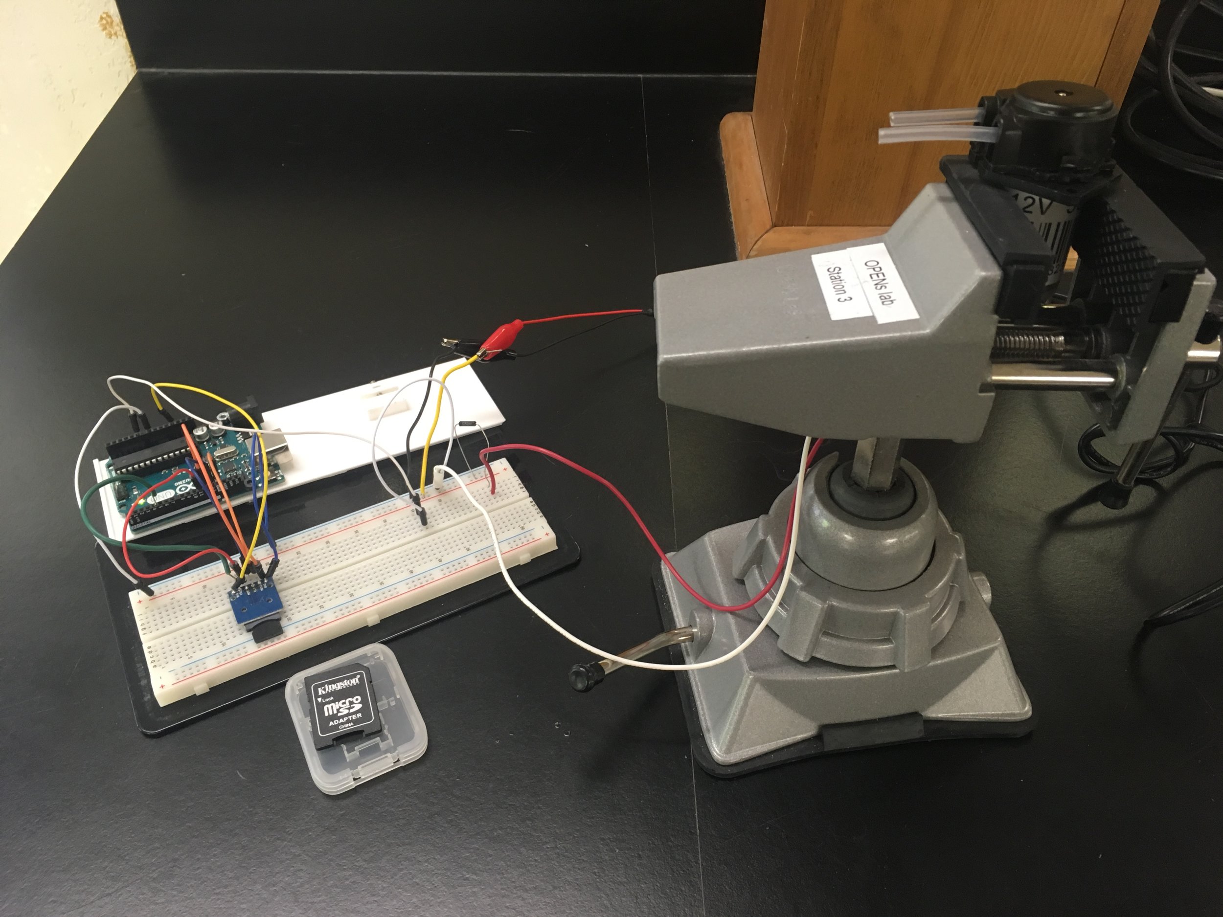
A pump is held in a clamp and powered from a 12v source. A .85 ohm, 1.4 watt rated resistor connects the pump to ground. The voltage across the .85 ohm resistor is measured over time using an arduino and this data is stored in an SD card.
The arduino reads the voltage on an analog pin and stores that, along with the time since starting in milliseconds, in the SD card. Initially there is a delay of one second in between data points and after sixty points the delay increases to one minute. This data will be transferred to a computer where it will be used to show the current through the pump over time.
// A simple voltage logger that is heavily
// based on the SD Datalogger example sketch.
#include <SPI.h>
#include <SD.h>
const int chipSelect = 4;
const int sensorPin = 0;
int n = 0;
void setup() {
Serial.begin(9600);
while(!Serial){
;
}
Serial.print(“Initializing SD card…”);
if(!SD.begin(chipSelect)){
Serial.println(“Card failed, or not present.”);
return;
}
Serial.println(“card initialized.”);
}
void loop() {
String dataString = makeDataString();
File dataFile = SD.open(“pumpLog.txt”, FILE_WRITE);
if(dataFile){
dataFile.print(dataString);
dataFile.close();
Serial.println(dataString);
}
else{
Serial.println(“error opening pumpLog.txt”);
}
if(n<60){
delay(1000);
n++;
}
else delay(60000);
}
String makeDataString(){
return String(analogRead(sensorPin)) + “, ” + String(millis()) + “; “;
}
Once the pump has run for two hours, the power will be turned off and the data from the SD card will be transferred to a computer. Using Ohm’s Law the voltage across the resistor will show the current through the system. The data will show what kind of trend, if any, the current draw has through the pump. It will also show if the current draw varies with a resolution of one minute.
This test will be repeated for two other pumps. Then it will be repeated with water flowing through the pump tube.
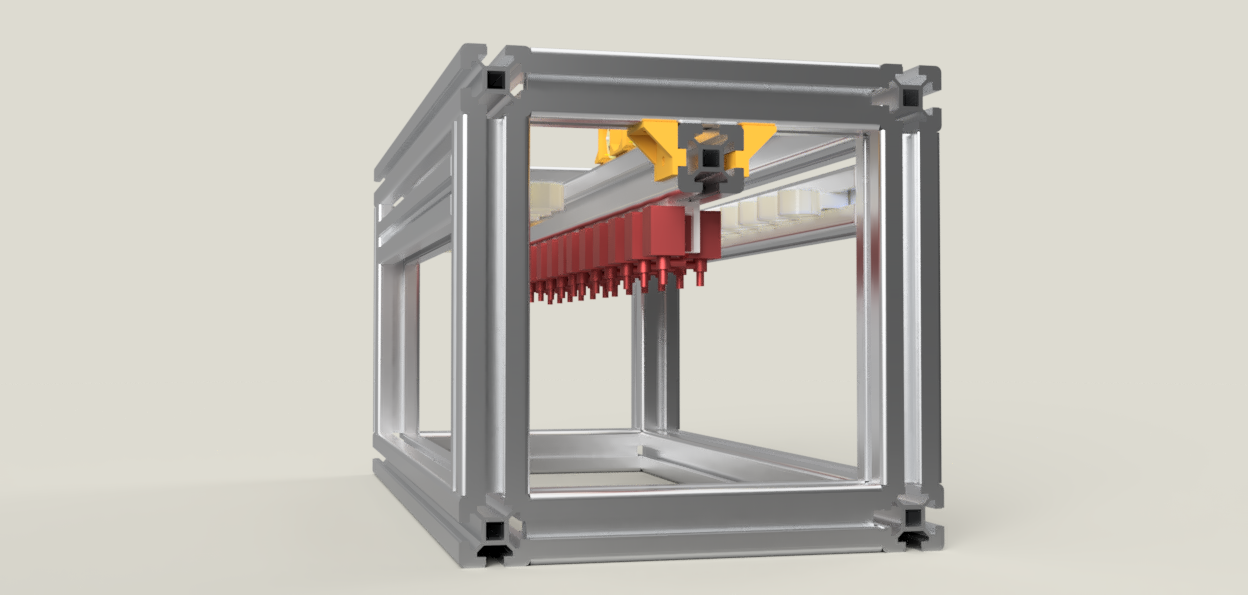
I finished the new design of the 24-bottle water sampler which will be fabricated within the next week before the electronics PCB gets here. The new design is made entirely out of 4040 (a 40 mm x 40 mm profile) extruded aluminum, common store-bought joints, and 3D printed components.
This redesign solves several issues with the original foam enclosure:
1. The 4040 frame does not require a laser cutter to manufacture
2. The frame is rigid
3. Mounting objects rigidly to the frame is very easy
This design uses 2 primary materials at the moment: 4040 extruded aluminum, and 3D printed ABS plastic. All of the printed parts could be replaced with machined mounts and brackets in the absence of a 3D printer. 4040 was chosen for the frame material because of its ease of use and because we have tons of it here at the lab, but future designs will most likely use slimmer extrusions like 2020 to save cost and weight.
Four long extrusions make up the outer corners of the frame. They are 600mm long, roughly corresponding to the 24 inch length of the original design. The short outer-frame pieces are all 210 mm long to provide enough space for the bags to hang. A 600mm length piece of 4040 runs across the top and provides channels to mount the valves, pumps, and electronics. Two 520mm lengths of 4040 across the sides, offset from the top by a few centimeters, provide the channels for the bag caps which the sample bags hang from.
The orange brackets are 3D printed and connect the central channel perpendicularly to to the frame. Other brackets are store-bought and aren’t included in the design. All mounting is done using t-nuts and/or t-bolts that slide in to the 4040 channel to limit the amount of machining required to assemble the sampler. A thin sheet of PETG plastic will cover the top of the assembly and protect the device from rain but could easily be replaced with a large trash bag or tarp.
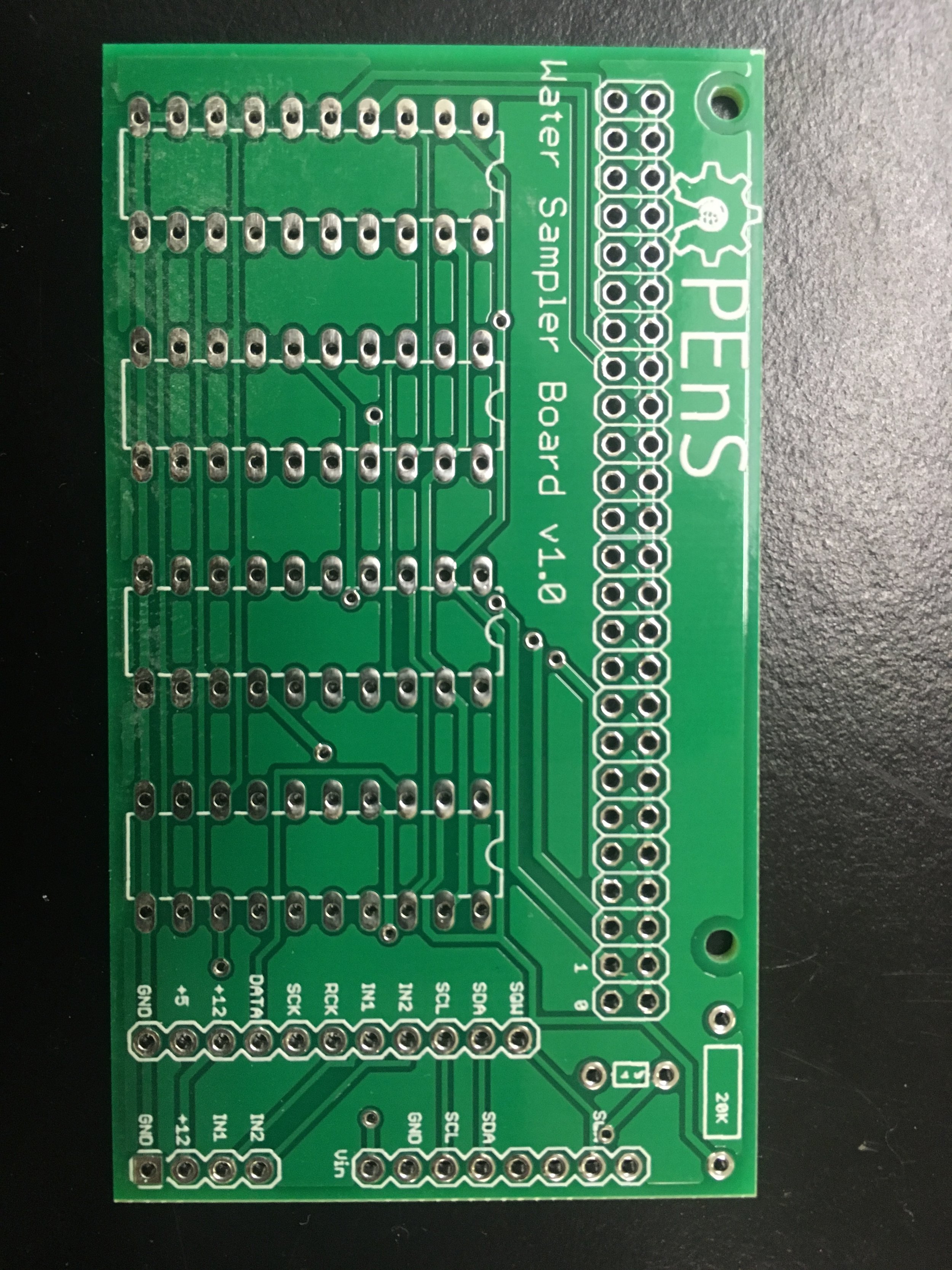
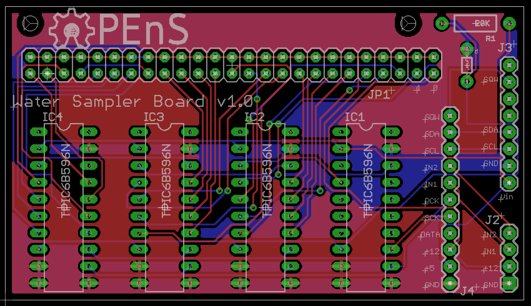
After lots of struggling with the current perf board electronics, we decided getting a PCB made was the way to go. The electronics have changed quite a bit since the last version so I started this one from scratch.
Changes include many more connections to the arduino, headers to connect the H-bridge and RTC breakouts, and removing the MOSFETs. The PCB includes a proper ground plane, our logo, and holes for mounting!
The primary benefit of moving to a PCB is the ability to use a rectangular connector on the board and insulation-displacement-connector for the ribbon cable, which means that we will be able to snap the 50-wire cable on and off the board. The quantity of connections made for a messy perf board and caused a lot of headaches while troubleshooting malfunctions. Despite the current setup working, it wouldn’t be reliable in the field.
There are a few changes I need to make to the design, such as optimizing the sizes of the VCC traces, but it should be sent out to be manufactured soon!
I’ve attached a video of the nearly finished water sampler’s ability to drain a sample without disconnecting the bag from the system. The current system is not proven to be air-tight and should not be expected to be so, but this will help to reduce error and eliminate the need to disassemble the tubing. Instead, the user can specify which bag to sample and run the pumps in reverse through serial commands through a computer console.
After about a week of waiting, the Adafruit DRV8871 H-bridge motor driver breakouts were delivered. They will replace the MOSFET circuit driving the pumps, which were allowing all kinds of noise and voltage spikes and caused the TPIC shift registers to reset every instance the pumps were switched on. Additionally, the previous electronics setup was mysteriously allowing the valves to leak water through to the sample bags when switched off. With the pumps being driven by the H-bridge, this problem has completely disappeared. The original cause was most likely related to the valves “soft resetting”, where each valve was neither completely off nor completely on after the pump was powered.
We just received an email today letting us know that the rest of the valves have finally shipped, which will allow us to completely assemble our 24 bag sampler! While we wait for that, I’ll be working on translating the electronics to a PCB and getting that printed. I’ll also be reviewing the design and adding more functionality to the code.
I recorded of a video of the system in action, included below, which is the first recorded successful test of our water sampler!
Several design decisions were made based on our pump parameters needed. For example, we need at least one meter of pump head and we need to be able to move water through roughly 5 meters of 3/16” (.476 cm) tubing (most likely there will be less tubing involved, but this is a good number to start with).
Through observation, I found that the throughput of a single pump at 1m head and room temperature was 50mL/min, or .83 cm^3/s, and the maximum suction head is greater than 1.5 meters, which was the highest I could place the pump without creating a more complex setup.
With a tubing cross sectional area of .71 cm^2, the velocity of the water in the tube being moved by the pump is about 1.2 cm / s. With such a small velocity, the head loss directly resulting from the 26 tee joints is about .76 cm, and the head loss from the friction of the tubing is even less than that.
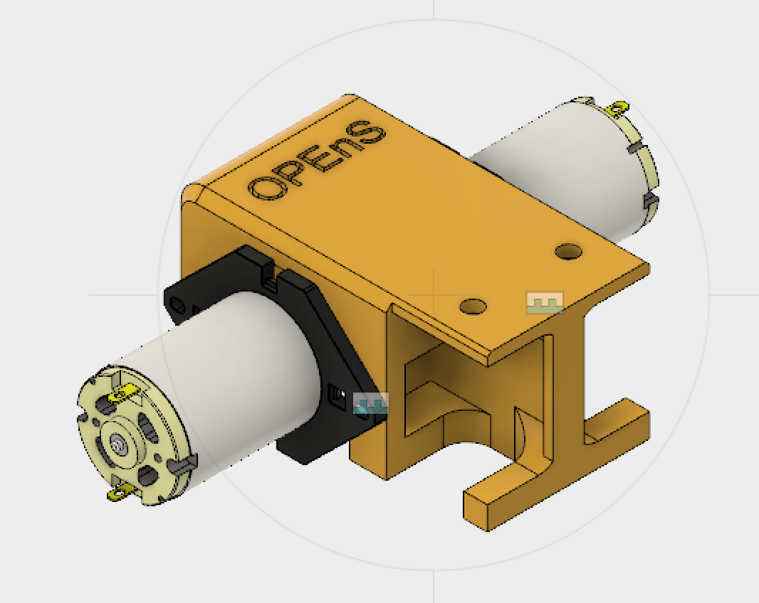
Because we don’t have to worry about head loss, and the max head one pump can provide exceeds our requirements, I decided that the design should combine two pumps in parallel to improve throughput rather than in series to improve head.
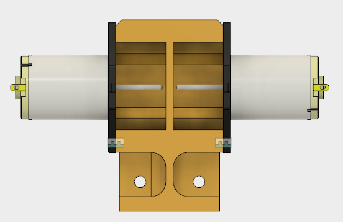
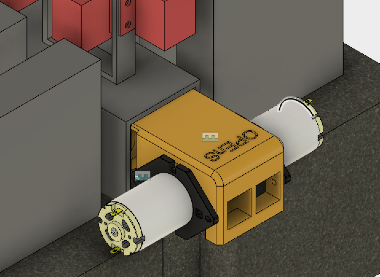
Now I could design the dual pump mount! I went with a design that mounted on the inside of the C-Channel spine, with the colinear, top-to-top facing pumps sticking out perpendicular to the c channel. The first 3D Print should be finished tomorrow! Pictures below.

I’ve completed two schematics for this project. The first is the base unit schematic (above). This is the main unit we will develop first. The schematic includes 8 valves (shown as inductors on the schematic) and one TPIC power shift register for controlling them. 6 lines are connected to a header: 5V, 12V, GND, SCK, DATA, and RCK. Because the base unit will have 24-31 bags for sampling, rather than 8, we will be using 4 TPICs in series on a single board to control a corresponding number of valves. The 3 additional TPICs will be connected in the same way shown in the extension unit schematic (below), only without headers in between sequential TPICS and only using one waste valve at the end.
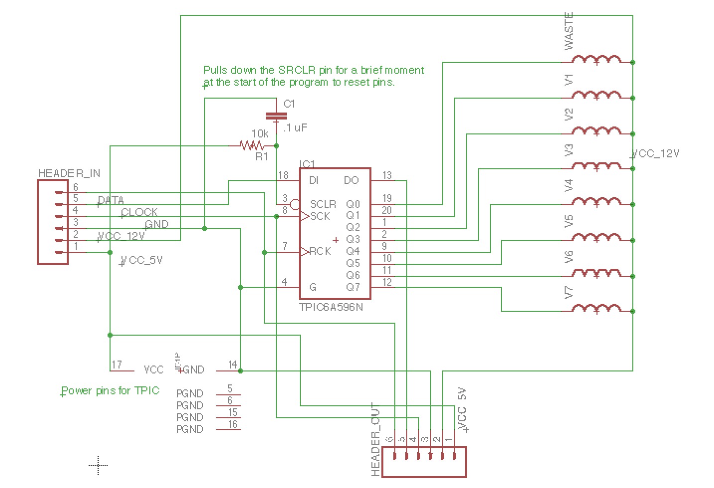
Eventually, extension units will allow additional samples without adding complexity to the process. 6 wires and one water line will connect the base unit to subsequent extension units, each with 24 bottles and an output line themselves.
The dummy switch, which is meant to represent a water probe that will be located at the end of each unit to check that water has flowed to the end. This is critical to the system’s sampling process: if the system tries to sample a specific amount of water based on the time the pumps are running, then it needs to know when to start timing. The probe will “short” like flipping a switch (though with much much more resistance) and send a low signal to a digital pin.
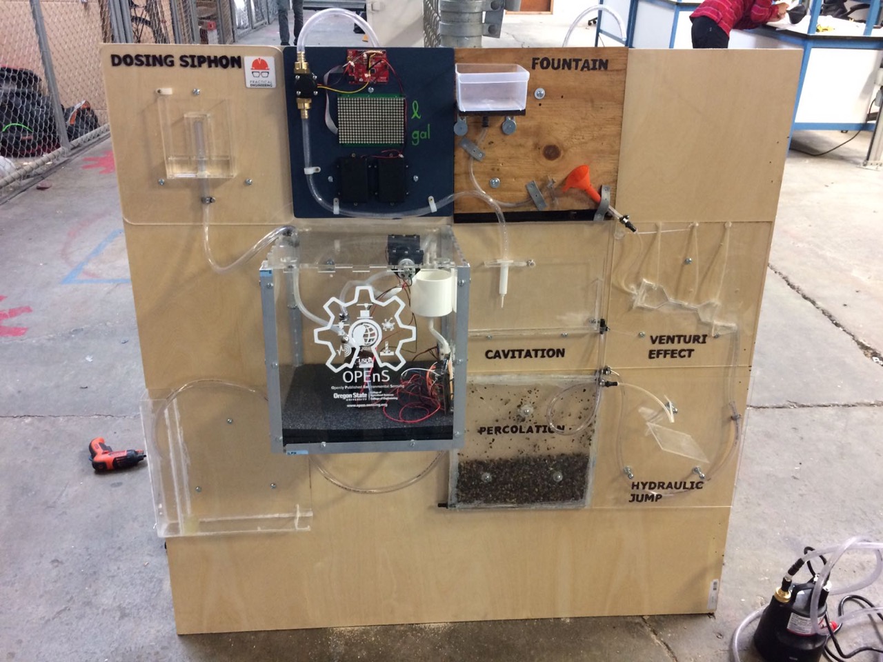
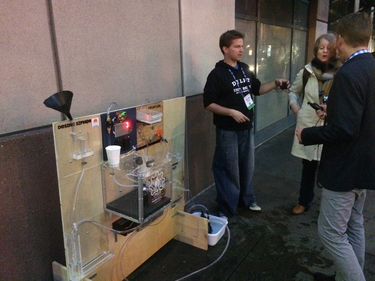
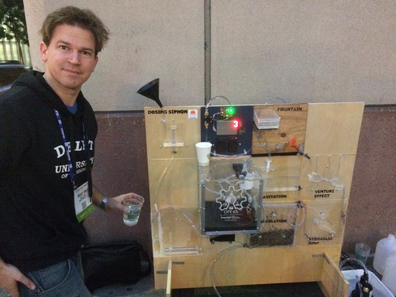
The OPEnS lab contributed a demonstration of the new water quality sampling system they are developing as part of a “Rube Goldberg” water machine that passed water from unit to unit. This was organized by Rolf Hut as a collaborative effort between institutions (each one contributing one or two units to the Rube Goldberg machine), and was widely seen by conference participants as “street art” immediately outside the conference. This was the first time such an effort had been tried, and brought many smiles, and much publicity for the OPEnS initiative.