Finalized Pole Attachment for Super Validator

The main body of the pole attachment has been done for some time, but getting the wires of the strain gauge through the tube was the lasting thing remaining. The main trouble was that the wires would only go through a section of the guiding tube and then get stuck. They now go through all the way very smoothly. 
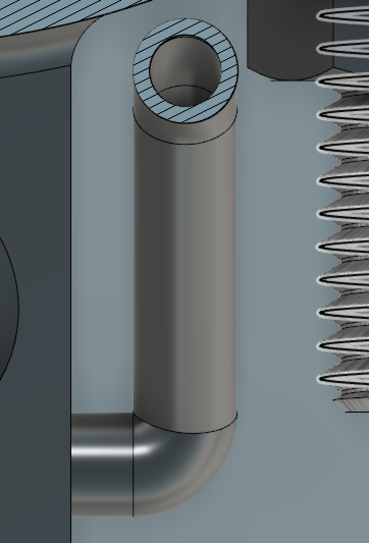

 First design with 90 degree corner First design with 90 degree corner

 First design with 90 degree corner


Second iteration with a smoother pathSecond iteration with a smoother path

Second iteration with a smoother path

The first iteration had a right angle that impeded the passage of the wires. It would only get through the hole but not through the corner. The logical next step was to reduce the amount of curvature that the wires had to go through. To work around this problem, I inserted a piece of wire through the top hole and soldered all the tips of the wires from the strain gauge together. I then pull the wire, and since all the wires were soldered to it, they all came through. This worked well but is not ideal. This is why further development was needed. 

The final design was different than what I was initially thinking about. There is no curve to the side instead there is loft coming from the side of the block in the form of a rectangle to a circle. This design makes it so that the wires don’t have to go through corners.  


Final design of wire guideFinal design of wire guide

Final design of wire guide


Cross section of wire guideCross section of wire guide

Cross section of wire guide

This is the iteration that will be used for testing in Kenya. Here is an interactive model of the piece:

Polev52 By Manuel Lopez Modelo »

Checkvalves… An update!

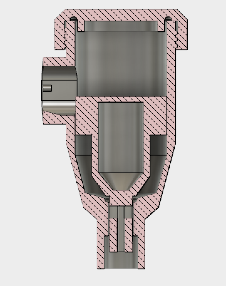
The rain catchment check valve was essentially shelved mid summer to move on to projects that showed more promise after poor performance of the design. Recently a researcher requested I send a couple check valves to her to set up in Kenya later in March, and so I decided to spend some time seeing if I could redesign the checkvalve in a more purposeful manner rather than trial and error, this time with more knowledge and resources (the Fusion3 F400 3D printer is so fast!). The purpose of the rain catchment check valve is to allow water through flow, while limiting the size of (ideally sealing) the drain to significantly reduce evaporation of collected water samples. The water flows from the TAHMO station to the checkvalve and drains into a collection bag.

This design would be based on a similar function as the last one: water flows into a chamber and raises a buoy, opening a drain that allows the water in the chamber to flow down and into the collection bag. I decided to incorporate an O-ring to assist in blocking the drain when little to no water is left in the chamber. While the original design allowed the buoy to be printed inside the chamber during the same print, using an o-ring meant the chamber and buoy should be printed as separate parts. This actually turned out to work better, anyways. In order to seal the top of the chamber a third part, the cap, would need to be made. I designed it to be twisted on the outside of the chamber’s top, pressing a large O-ring against the top edge of the chamber with enough force to form a watertight seal. 

To connect to the TAHMO station, the side opening slides over the TAHMO’s spout and a long ziptie is looped around the TAHMO station and the valve’s outer wall, pressing the two together. This means the water enters the chamber at a low velocity and angle, which is significant because the momentum of the water is directed nearly horizontally and initially at the top of the buoy. This means the force on the buoy from the flowrate of the water acts to tilt it off of its seal rather than add force to the seal of the O-ring.

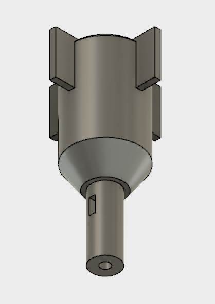
One of the largest issues in the original design was the buoy’s lack of a correcting method after being tilted. There were two ways I could fix this: place the center of mass of the buoy as low as possible, and to find a way to limit its movement to the vertical axis. While I kept the first option in mind, such a small mass (<3g) can easily be overcome by small pressures such as a water droplet or a defect in the print. The fins on the side of the buoy act to prevent more than a couple degrees tilting.

The main problems to overcome are friction and catching on the sides of the chamber walls. Some dimensions require adjusting to properly fit onto the TAHMO station. Overall, this design works significantly better than the previous version.

Printed Super Calibrator System

The system has been printed. There are so minor flaws with will be addressed, but we have our first prototype. 


3D printed Validator and pole attachment&nbsp;3D printed Validator and pole attachment&nbsp;

3D printed Validator and pole attachment 

In the image above we can see both of pieces that are 3D printed. The pole attachment is locked to a piece of aluminum extrusion just for demonstration purposes; it also has a battery sitting on it to keep it from falling. Our validator has a 6mm hole diameter siphon and will drain all the container in about 50-55 seconds. An ADC will be amplifying the signal coming from the strain gauge and outputting data to an Arduino UNO. All the electronics will be located on top of the pole attachment.

The flaws that were previously mentioned were about the attachment. The holes for the u-bolt are a little bit too close so I had to drill them out to get the u-bolt to fit. Another thing that will be changed is the little tube on the side that guides the wires coming from the strain gauge. It has a 90-degree corner that makes it difficult to pass wires through it, so I will modify the design to make it smoother. Other than that, our desing is complete. 

Super Validator Model and Electronics

After many tests to figure out what would work out the best, we have chosen our best design. We will be using a 6mm diameter hole for the siphon, this will be sufficient for what we need it to do. I have been able to put together a model of the whole system to be able to visualize the prototype. Here is a rendering of the Super Validator configuration: 


Super Validator systemSuper Validator system

Super Validator system

This model only has the parts that will be 3D printed, the electronics will be sitting on the part that is attached to the pole. The electronics consist of a strain gauge connected to an ADC that will be sending data to an arduino.


Electronics setupElectronics setup

Electronics setup

The electronics have been calibrated and tested. We are currently printing both the validator and the pole attachement, and will soon have the first working prototype. 

Super Validator 7mm

After running the test we were able to conclude that the 8mm diameter hole is too big to create the siphon at the slowest rate on the OPEnS Calibrator. 6mm diameter hole works just fine but takes a little more time than what we want it to. We are going to try a 7mm diameter hole and see how it performs. If this does not work, we will move to other designs. Here are links to the other designs we will try:


We will replicate design B. Designs &nbsp;A &amp; C &nbsp;are similar to what we have already.&nbsp;We will replicate design B. Designs &nbsp;A &amp; C &nbsp;are similar to what we have already.&nbsp;

We will replicate design B. Designs  A & C  are similar to what we have already. 


http://makezine.com/projects/make-35/ctesibius-and-the-tantalus-cup/


Super Validator Testing

We have created three working prototypes of the validator. The main difference between each of these is the diameter of the hole that siphons the water out. We are currently working with 4mm, 6mm, and 8mm diameter holes.

We wanted to drain the validator in about 30 secs, if possible. We started by printing a 4mm diameter hole for the siphon but that turned out to be insufficient. We went on to make a 6mm diameter hole and it performed better but not quite as we wanted it to. After that iteration, we made an 8mm diameter and it worked great, with such wide orifice came a drawback.

To test the performance of each of the validators we used the OPEnS Calibrator; it was set to the lowest setting which is the 30 min setting. I initially filled the each validator with 500ml of water and then added more water to reach a height of about 1cm below the siphon’s top. The calibrator was then placed on an o-ring stand above the validator and left to filled the validator the rest of way. 


The rest of this post will discuss each of the validators performance and show the videos of the trials. 

The 4mm diameter has troubles creating the siphon but after it is established it works just fine. For some reason, the siphon is not created and we need to push the water into the hole to get it started. This validator takes about 2mins and 20 secs to drain itself. 

The 6mm diameter validator works just fine. The only thing that restricts the flow of water is the mesh that it has at the inlet and outlet of water, created to keep bugs away. With both meshes, it drains in 1min 35sec. With only the inside mesh, it drains in 1min 18sec. Having no mesh at all lets it drain in about 50sec. This version can create the siphon effect at the rate the water is coming down from the OPEnS Calibrator.  

The 8mm diameter validator drains the fastest; it will drain in about 20-25 sec. The only problem with this is that the water flow coming into the validator has to be really high otherwise, the siphon can not be established. The flow of water coming down from the OPEnS calibrator is not enough to commence the siphon effect, so the water only really trickles out of the validator. 

Pythagorean Rain Validator

The rain validator needs to be drained after it reaches its maximum capacity. To do this we implemented the Pythagorean Cup principal. This allows for our validator to reach a certain liquid capacity and then drain. The principal is quite simple; the liquid is permitted to rise to a certain level and when the point is reached, a siphon will drain will the container. 


Rain Validator CAD rendering 

Section Analysis of the Rain Validator using Fusion360

Our design works but needs modifications to be able to work appropriately. The following video is a demonstration of the current desing. 

New Rain Validator Experiment


Today I set up a new experiment using the old HP tablet and OHAUS usb scales. The setup was three scales connected to the tablet, which was running Jim Wagner’s custom logging software, ScaleWatcher v3. A beaker filled nearly to the top, a wickless validator filled nearly to the top, and a validator with wick saturated and filled nearly to the top with water will have their masses logged every 10 minutes for a month or until the validators are dry. The wicked validator has a dry weight of 191 grams, while the wickless validator has a dry weight of 75 grams. The beaker and wicked validator are on 4000g scales and the wickless validator is on a 600g scale.


Posted by Mitch

Transferring CAD of Rain Catcher Calibrator from OpenSCAD to Fusion360

Fusion360 a smarter tool for makers and professionals to use when making parametric designs. It uses a GUI to input the parameters and doesn’t require any previous knowledge in programming.  I have decided to transfer the design over. This will make it easier to modify when the user downloads our files, especially if they don’t have any programming experience.


Updated Validator Data

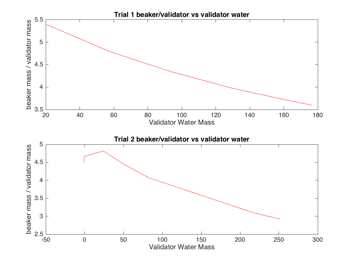
After another day of data, I created another set of graphs that displayed the relationship between the ratio of beaker mass to validator mass and validator’s water mass (calculated by subtracting the dry weight of the validator from each data point), per Selker’s request. What this graph shows is that the validator’s water evaporates at a faster rate relative to the validator’s total mass than the water in the beaker. Below is the set of graphs for trial 1 and trial 2.


ratio vs val waterratio vs val water