Pumps and Pump Mounting

Several design decisions were made based on our pump parameters needed. For example, we need at least one meter of pump head and we need to be able to move water through roughly 5 meters of 3/16” (.476 cm) tubing (most likely there will be less tubing involved, but this is a good number to start with).

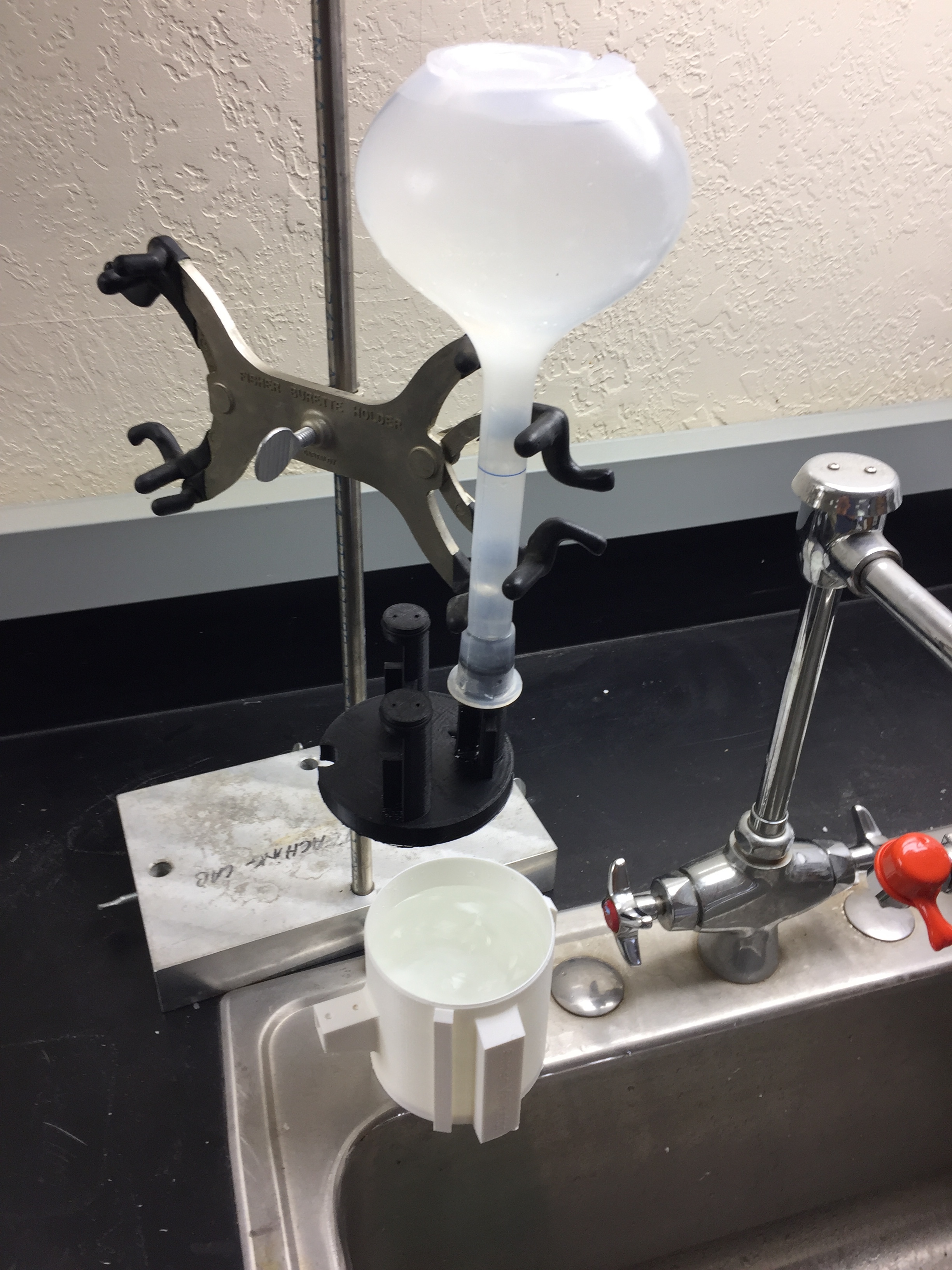
Through observation, I found that the throughput of a single pump at 1m head and room temperature was 50mL/min, or .83 cm^3/s, and the maximum suction head is greater than 1.5 meters, which was the highest I could place the pump without creating a more complex setup. 

With a tubing cross sectional area of .71 cm^2, the velocity of the water in the tube being moved by the pump is about 1.2 cm / s. With such a small velocity, the head loss directly resulting from the 26 tee joints is about .76 cm, and the head loss from the friction of the tubing is even less than that. 

Because we don’t have to worry about head loss, and the max head one pump can provide exceeds our requirements, I decided that the design should combine two pumps in parallel to improve throughput rather than in series to improve head. 

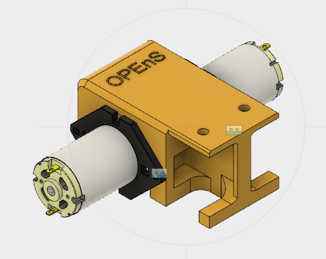
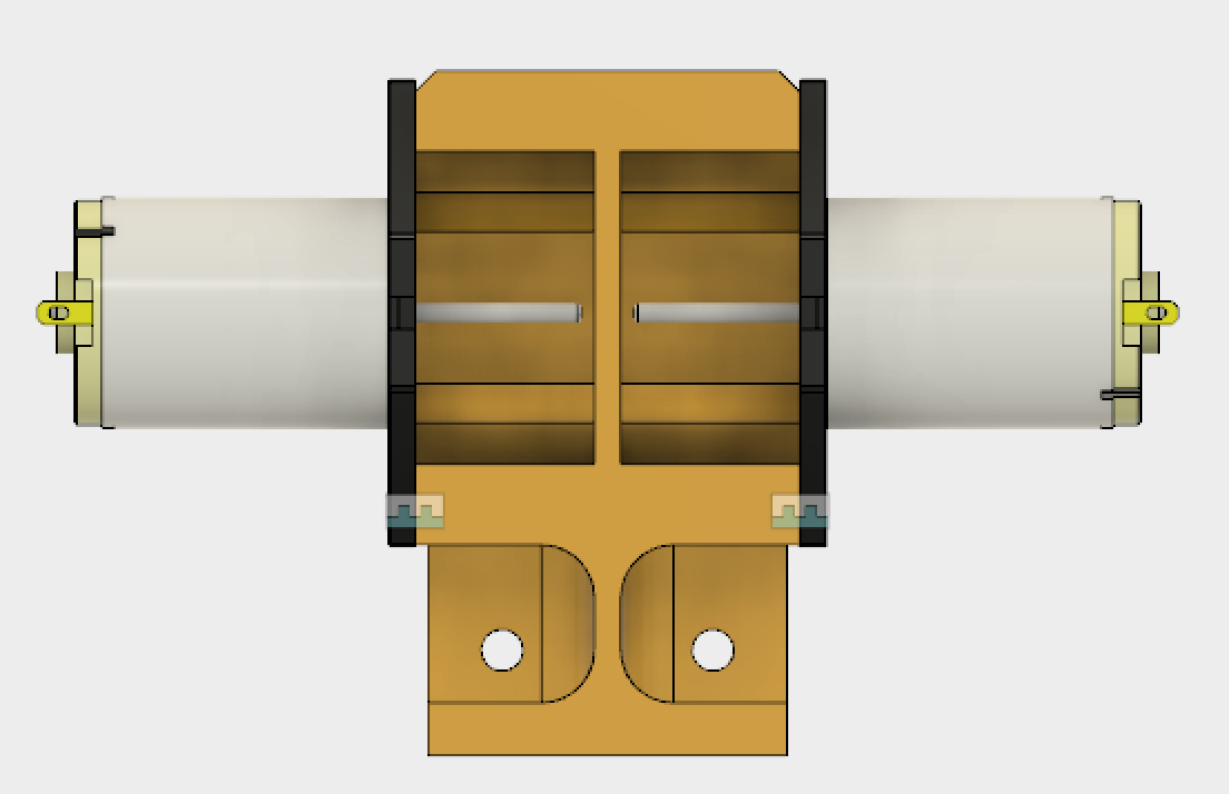
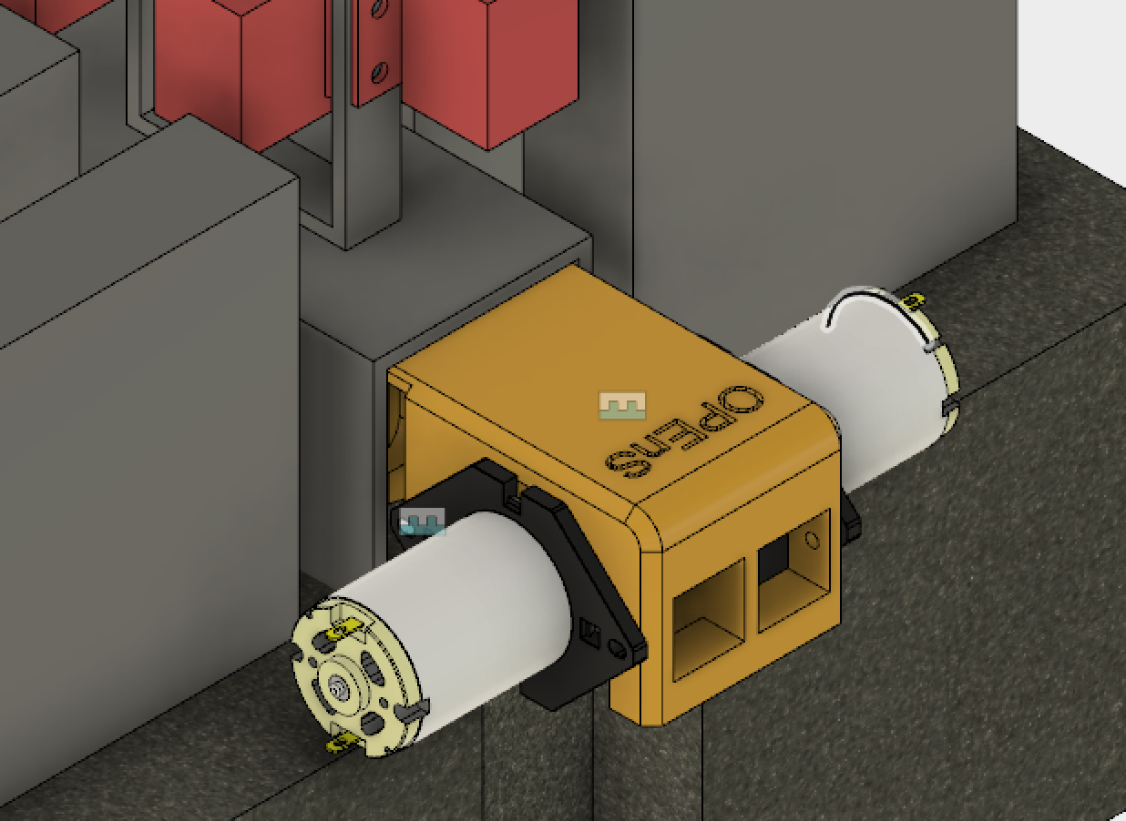
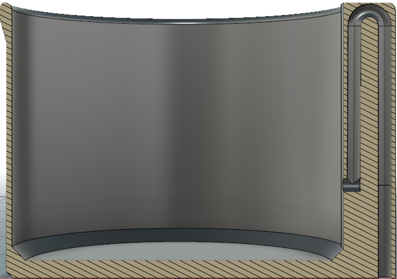
Now I could design the dual pump mount! I went with a design that mounted on the inside of the C-Channel spine, with the colinear, top-to-top facing pumps sticking out perpendicular to the c channel. The first 3D Print should be finished tomorrow! Pictures below.


twopumpmount.jpgtwopumpmount.jpg


twopumpmount2twopumpmount2


twopumpmount3twopumpmount3

Super Validator 7mm

After running the test we were able to conclude that the 8mm diameter hole is too big to create the siphon at the slowest rate on the OPEnS Calibrator. 6mm diameter hole works just fine but takes a little more time than what we want it to. We are going to try a 7mm diameter hole and see how it performs. If this does not work, we will move to other designs. Here are links to the other designs we will try:


We will replicate design B. Designs  A & C  are similar to what we have already. We will replicate design B. Designs  A & C  are similar to what we have already. 

We will replicate design B. Designs  A & C  are similar to what we have already. 


http://makezine.com/projects/make-35/ctesibius-and-the-tantalus-cup/


WSAN Pro Trinket 3V Shield Schematics

By: Chet Udell

First versions of Pro Trinket 3V Shield Schematics Are Here!


One shield is for the receiver hub (aka Gateway) and won’t change too much except for exploring different terminal protocols for the Gateway (e.g. Direct to computer serial like thi one, vs WiFi, LoRa, and Bluetooth). Basically, only the header for the nRF24L01+ was needed.


The other shield is a general-purpose i2c (designed with the MPU6050 3-axis accel + 3-axis gyro in mind, but can take any i2C device) with 3 general purpose Analog inputs. A custom circuit on the Analog input lines enables a choice of either using a 2-wire voltage divider (variable resistor) sensor, or a 3-pin powered sensor (takes 3V, GND, and outputs analog signal). This is meant to serve a wide multitude of general sensing purposes, where one may also choose to not populate the analog or i2c headers if not being used. Also comes with a LiPo JST battery connector, power switch. Header for nRF24L01+ also required.

Super Validator Testing

We have created three working prototypes of the validator. The main difference between each of these is the diameter of the hole that siphons the water out. We are currently working with 4mm, 6mm, and 8mm diameter holes.

We wanted to drain the validator in about 30 secs, if possible. We started by printing a 4mm diameter hole for the siphon but that turned out to be insufficient. We went on to make a 6mm diameter hole and it performed better but not quite as we wanted it to. After that iteration, we made an 8mm diameter and it worked great, with such wide orifice came a drawback.

To test the performance of each of the validators we used the OPEnS Calibrator; it was set to the lowest setting which is the 30 min setting. I initially filled the each validator with 500ml of water and then added more water to reach a height of about 1cm below the siphon’s top. The calibrator was then placed on an o-ring stand above the validator and left to filled the validator the rest of way. 


The rest of this post will discuss each of the validators performance and show the videos of the trials. 

The 4mm diameter has troubles creating the siphon but after it is established it works just fine. For some reason, the siphon is not created and we need to push the water into the hole to get it started. This validator takes about 2mins and 20 secs to drain itself. 

The 6mm diameter validator works just fine. The only thing that restricts the flow of water is the mesh that it has at the inlet and outlet of water, created to keep bugs away. With both meshes, it drains in 1min 35sec. With only the inside mesh, it drains in 1min 18sec. Having no mesh at all lets it drain in about 50sec. This version can create the siphon effect at the rate the water is coming down from the OPEnS Calibrator.  

The 8mm diameter validator drains the fastest; it will drain in about 20-25 sec. The only problem with this is that the water flow coming into the validator has to be really high otherwise, the siphon can not be established. The flow of water coming down from the OPEnS calibrator is not enough to commence the siphon effect, so the water only really trickles out of the validator. 

Schematics!

I’ve completed two schematics for this project. The first is the base unit schematic (above). This is the main unit we will develop first. The schematic includes 8 valves (shown as inductors on the schematic) and one TPIC power shift register for controlling them. 6 lines are connected to a header: 5V, 12V, GND, SCK, DATA, and RCK. Because the base unit will have 24-31 bags for sampling, rather than 8, we will be using 4 TPICs in series on a single board to control a corresponding number of valves. The 3 additional TPICs will be connected in the same way shown in the extension unit schematic (below), only without headers in between sequential TPICS and only using one waste valve at the end. 


Screen Shot 2017-01-24 at 4.04.53 PM.pngScreen Shot 2017-01-24 at 4.04.53 PM.png

Eventually, extension units will allow additional samples without adding complexity to the process. 6 wires and one water line will connect the base unit to subsequent extension units, each with 24 bottles and an output line themselves. 


The dummy switch, which is meant to represent a water probe that will be located at the end of each unit to check that water has flowed to the end. This is critical to the system’s sampling process: if the system tries to sample a specific amount of water based on the time the pumps are running, then it needs to know when to start timing. The probe will “short” like flipping a switch (though with much much more resistance) and send a low signal to a digital pin.

OPEnS Water Sampler Debut @ AGU 2016

By: Chet Udell

The OPEnS lab contributed a demonstration of the new water quality sampling system they are developing as part of a “Rube Goldberg” water machine that passed water from unit to unit.  This was organized by Rolf Hut as a collaborative effort between institutions (each one contributing one or two units to the Rube Goldberg machine), and was widely seen by conference participants as “street art” immediately outside the conference.  This was the first time such an effort had been tried, and brought many smiles, and much publicity for the OPEnS initiative.


Powering up!

Author: Chet Udell

We received our Cottonwood UHF RFID reader today and are powering it up as we wait on our moisture RFID tags to arrive from SMARTEC.

Pythagorean Rain Validator

The rain validator needs to be drained after it reaches its maximum capacity. To do this we implemented the Pythagorean Cup principal. This allows for our validator to reach a certain liquid capacity and then drain. The principal is quite simple; the liquid is permitted to rise to a certain level and when the point is reached, a siphon will drain will the container. 


Rain Validator CAD rendering 

Section Analysis of the Rain Validator using Fusion360

Our design works but needs modifications to be able to work appropriately. The following video is a demonstration of the current desing. 

New Laser Cutter Lens

The laser cutter came with another lens that we were totally unaware of its existence. Why would such expensive machine be missing one of its main parts? Looking through an accessories box of the laser cutter, I came across a little box that contained something wrapped in white paper- it was the other lens! The lens that we were using would only cut when it was in the metal-cutting position, even though we were not cutting metals. This new lens can cut in the non-metal and metal positions. 

New lens 

The very first thing that I tested  was if it could cut in the non-metal-cutting position. After that, I proceeded to test cardboard, plexiglass, and foam.When cutting foam we were getting beveled cuts. This was the main reason we considered buying to new lens to get better cuts. 

 Circle and rectangle test cuts with new lens. Of each set, the left pieces were cut with the old lens and right pieces with new     lens.

We can observe that the new lens can cut straight down the foam without creating a bevel. This is exactly the type of quality we need and expected from such a laser cutter. With our old lens it was really hard trying to get a straight cut; we got pretty close but nothing compared to this new lens.

Rube Goldberg Project Box

Making this box is not as simple as I initially thought. One of the most time-consuming parts of this box is making the finger joints. After making the finger joints the rest of the process was very smooth. 


CAD rendering of the box in acrylicCAD rendering of the box in acrylic

CAD rendering of the box in acrylic


Finger joint designFinger joint design

Finger joint design

The CAD was the first thing that was done and then DXF files were exported to the laser cutter. The first prototype of the box was made out of cardboard to make sure all of the sides would fit perfectly- not too wiggly and not too tight. 

The DXF files are the surfaces sketches of each of the faces of the box. These files are the ones that are processed into the commands that the laser cutter uses to position the laser. Having the CAD finished makes it easy to produce these files because we just pull them off the faces of our designs. 


Cardboard prototype 

We also did our first tests etching on cardboard. The OPEnS logo was the design that we used for our testing and it came out very well. 

First cardboard etching test