By: Chet Udell
Introducing a new, modular, open-source, open-hardware wireless sensor-actuator network toolkit for environmental and agricultural projects. The main idea is: may people in environmental and agricultural fields have need for (or could greatly benefit from) deploying sensor-actuator systems in their practice. However, the exact system of sensors for each individual is idiosyncratic to their unique environment, constraints, and line of inquiry, requiring customs systems be designed from scratch for each new project. This results in a barrier to entry for those who don’t have the background or time to learn and develop their own sensor-actuator systems. OPEnS WSAN proposes a plug and play, modular, reconfigurable architecture that would enable those with little-to-no expertise in engineering to quickly map out and assemble a unique system to fit their needs in relatively little time.
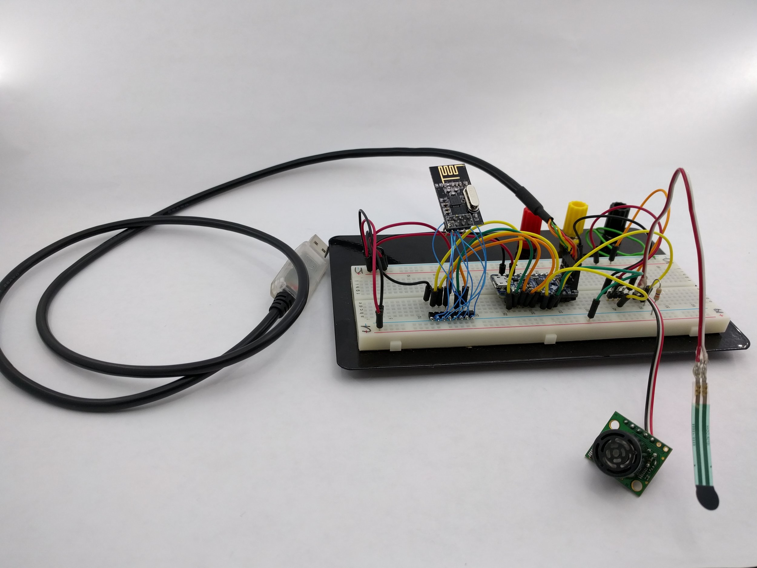
Transmitter prototype with Adafruit Pro Trinket 3V, nRF24L01+, with Sonar and FSR sensors.
Hub
A single hub will collect all transmitted data from nodes and translate data streams into WiFi for uploading onto a cloud storage service.
Sensor Nodes
Will be comprised of parents and children. There can be up to 6 unique parents directly connected to the hub. Children placed further away can communicate to the hub by passing messages along to their parent.
Actuator nodes
These nodes will receive commands from the hub to drive relays, motors, servos, valves, and other commonly used actuators. Messages may be sent in real time by the user sending commands to the hub, or automated through a cloud service like IFTTT (If This Then That). In this manner, hub may be programmed to alter the behavior of sensors or trigger events of actuators based on the behavior or events from other nodes.
Repeater Nodes
These simply extend the range of communication of nodes to the hub by relaying messages to their target destination.
Library
I’m using the RF24Network library by maniacbug, which can be accessed on GitHub, or through the Arduino IDE Library manager. I’m also using the i2cdev library by jrowberg to manage communication with the MPU6050 IMU sensor (see below).
Progress to Date
I’ve begun preliminary work on evaluating the Nordic nRF24L01+ wireless transceiver radios with the Arduino Uno and Adafruit Pro Trinket 3V. These ultra-low power radios give significant range and adjustable data rate down to 250kbps. The datasheet is here. 2 sensor transmitters and one hub now work, will add more when more nRF radios arrive in the mail.
Sensors supported so far
- MaxBotix EZ-XL 1cm resolution sonar sensor
- Small Force Sensitive Resistor
- Flex Sensor
- Photo Resistor
- MPU6050, 6-axis inertial measurement unit (IMU)
Actuators
- None yet