Hello all, I just completed and published a how-to guide that walks you through how to use an Arduino to send an RSSI inventory command from the Cottonwood and published it to Instructables. It is available here so check it out!
The main body of the pole attachment has been done for some time, but getting the wires of the strain gauge through the tube was the lasting thing remaining. The main trouble was that the wires would only go through a section of the guiding tube and then get stuck. They now go through all the way very smoothly.
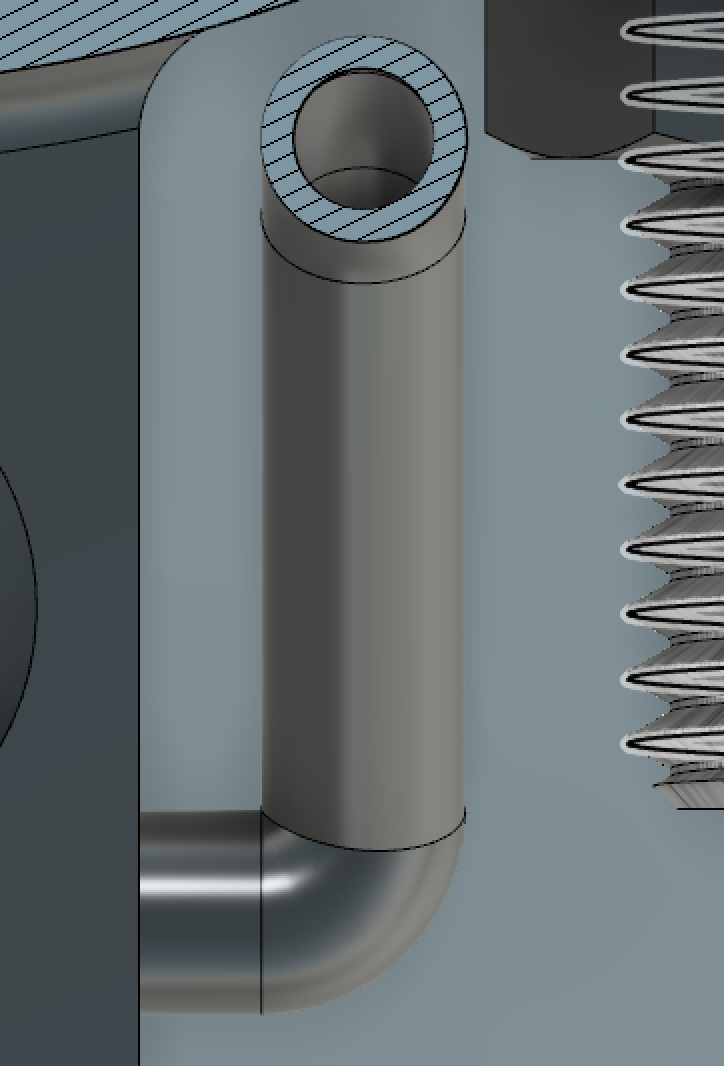
First design with 90 degree corner
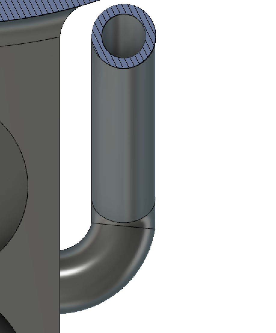
Second iteration with a smoother path
The first iteration had a right angle that impeded the passage of the wires. It would only get through the hole but not through the corner. The logical next step was to reduce the amount of curvature that the wires had to go through. To work around this problem, I inserted a piece of wire through the top hole and soldered all the tips of the wires from the strain gauge together. I then pull the wire, and since all the wires were soldered to it, they all came through. This worked well but is not ideal. This is why further development was needed.
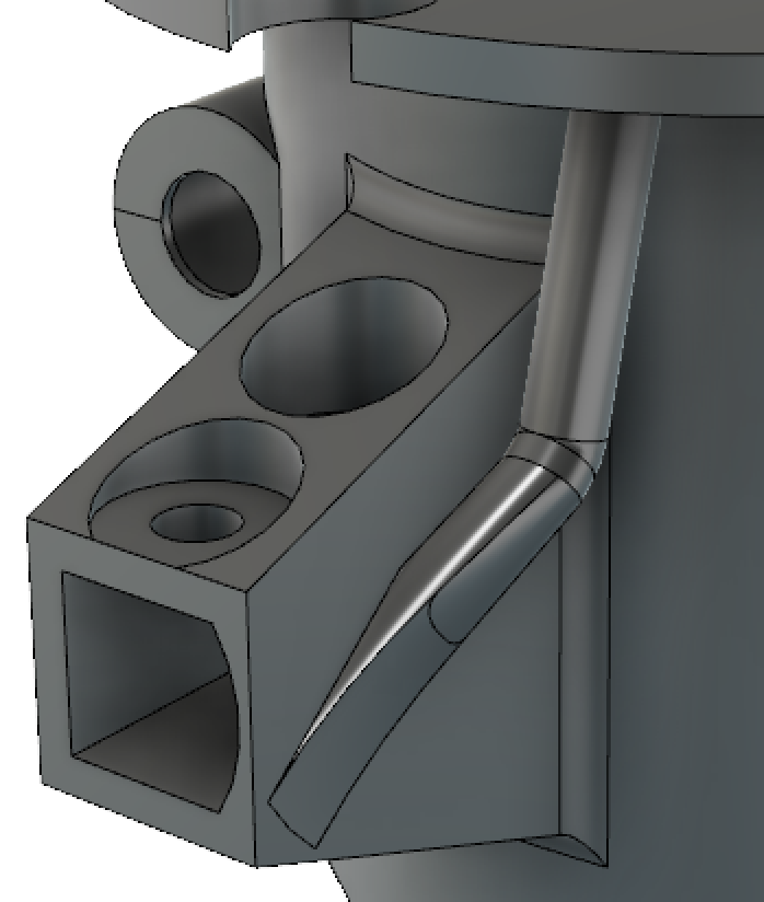
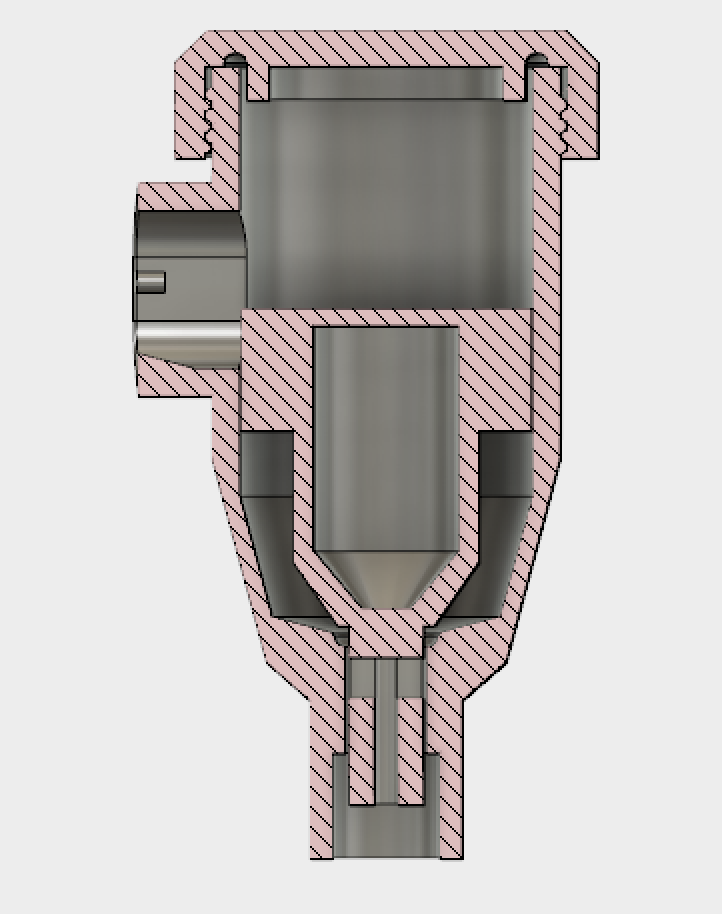
The final design was different than what I was initially thinking about. There is no curve to the side instead there is loft coming from the side of the block in the form of a rectangle to a circle. This design makes it so that the wires don’t have to go through corners.
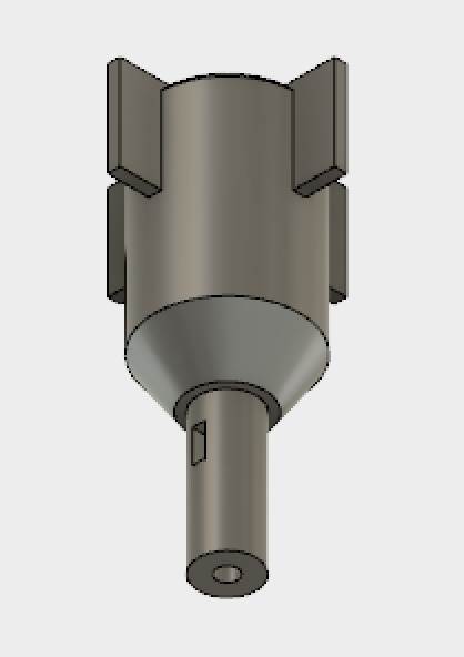
Final design of wire guide
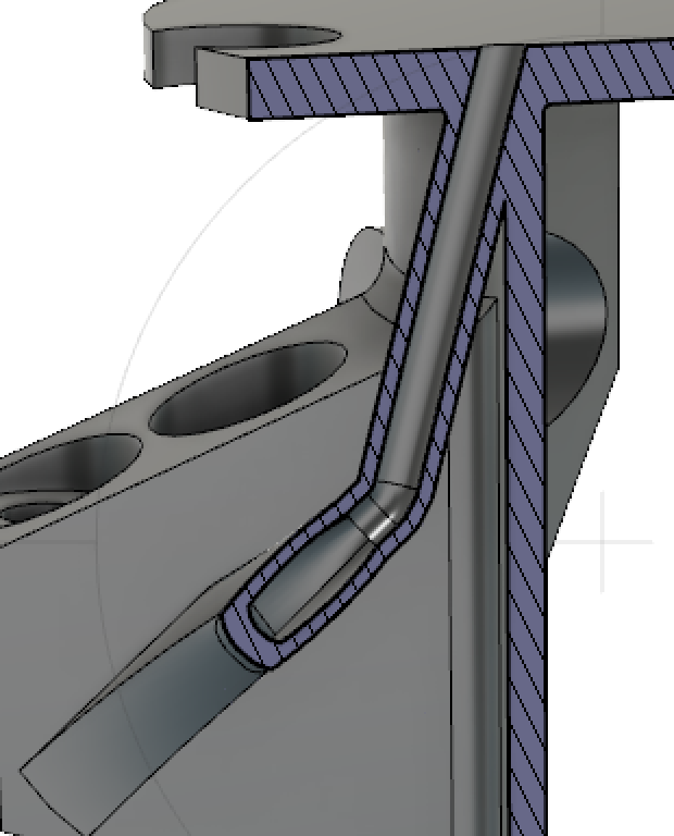
Cross section of wire guide
This is the iteration that will be used for testing in Kenya. Here is an interactive model of the piece:
The rain catchment check valve was essentially shelved mid summer to move on to projects that showed more promise after poor performance of the design. Recently a researcher requested I send a couple check valves to her to set up in Kenya later in March, and so I decided to spend some time seeing if I could redesign the checkvalve in a more purposeful manner rather than trial and error, this time with more knowledge and resources (the Fusion3 F400 3D printer is so fast!). The purpose of the rain catchment check valve is to allow water through flow, while limiting the size of (ideally sealing) the drain to significantly reduce evaporation of collected water samples. The water flows from the TAHMO station to the checkvalve and drains into a collection bag.
This design would be based on a similar function as the last one: water flows into a chamber and raises a buoy, opening a drain that allows the water in the chamber to flow down and into the collection bag. I decided to incorporate an O-ring to assist in blocking the drain when little to no water is left in the chamber. While the original design allowed the buoy to be printed inside the chamber during the same print, using an o-ring meant the chamber and buoy should be printed as separate parts. This actually turned out to work better, anyways. In order to seal the top of the chamber a third part, the cap, would need to be made. I designed it to be twisted on the outside of the chamber’s top, pressing a large O-ring against the top edge of the chamber with enough force to form a watertight seal.
To connect to the TAHMO station, the side opening slides over the TAHMO’s spout and a long ziptie is looped around the TAHMO station and the valve’s outer wall, pressing the two together. This means the water enters the chamber at a low velocity and angle, which is significant because the momentum of the water is directed nearly horizontally and initially at the top of the buoy. This means the force on the buoy from the flowrate of the water acts to tilt it off of its seal rather than add force to the seal of the O-ring.
One of the largest issues in the original design was the buoy’s lack of a correcting method after being tilted. There were two ways I could fix this: place the center of mass of the buoy as low as possible, and to find a way to limit its movement to the vertical axis. While I kept the first option in mind, such a small mass (<3g) can easily be overcome by small pressures such as a water droplet or a defect in the print. The fins on the side of the buoy act to prevent more than a couple degrees tilting.
The main problems to overcome are friction and catching on the sides of the chamber walls. Some dimensions require adjusting to properly fit onto the TAHMO station. Overall, this design works significantly better than the previous version.
For the last week, I worked on evaluating the potential of the ESP8266 as a WiFi communication device. It is a cheap WiFi module that is well-documented and thus suited to our project.
This is a guide that compiles and clarifies a few different sources into one to set up and ESP and Arduino Uno as a web server. If connected to the same network as the ESP, you can visit its IP address and see a customizable web page. This is a cheap and easy implementation that can be used for an Internet of Things project.
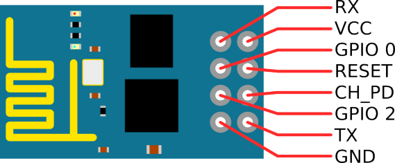
My starting point was an Arduino forum. First, I wired up the ESP and the Arduino, using this image as reference. Note: your board may say IO0 and IO2 rather than GPIO 0 and 2. Additionally, some boards may denote an EN pin instead of CH_PD pin.
Wiring:
I wired it up like this:
Arduino Pin ———- ESP Pin
2 ———————– TX
3 ———————– RX
GND ——————- GND
3.3V ——————– 3.3V (or 3V3)
3.3V ——————– CH_PD (or EN)
If you use the Arduino’s RX and TX pins directly, wire the ESP RX to the Arduino TX and the ESP TX to the Arduino RX. If you use these pins directly, you may need to disconnect them from the ESP when uploading your code, as these are used to upload code from the computer to the Arduino.
You will likely have to wire wrap, solder, or buy an ESP with headers added on to it, as it cannot be placed directly on the breadboard in its original form (this will connect the two rows of pins on the ESP to each other).
Code:
Once wired, upload the code available here. Note, this code has been borrowed and slightly modified (comments added and syntax error fixed) from allabouteee.com.
Information, original code, and guide video can be found at a post on allabouteee.com
Caveat: If using this code, note that lines 26-32 are commented out and can be removed. Additionally, lines 49 and 60 should be updated with variable name cipSend, rather than the incorrect cipsend.
AT-Command Information:
The setup in the code used several AT-commands to reset the ESP, set it up as a wireless access point, and get information from it. More detail about these can be found at itead’s AT command page. They can be used to update ESP firmware, change the SSID, add a password, etc.
LoRa is a Low Power Wide Area Network (LPWAN) hardware set for creating long range (2km to 10s of kilometers) star or star-of-star networks. OPEnS Lab is evaluating LoRa for on of it’s 4 Internet of Ag communication options (others being close-range RF (100m), WiFi, and GSM).
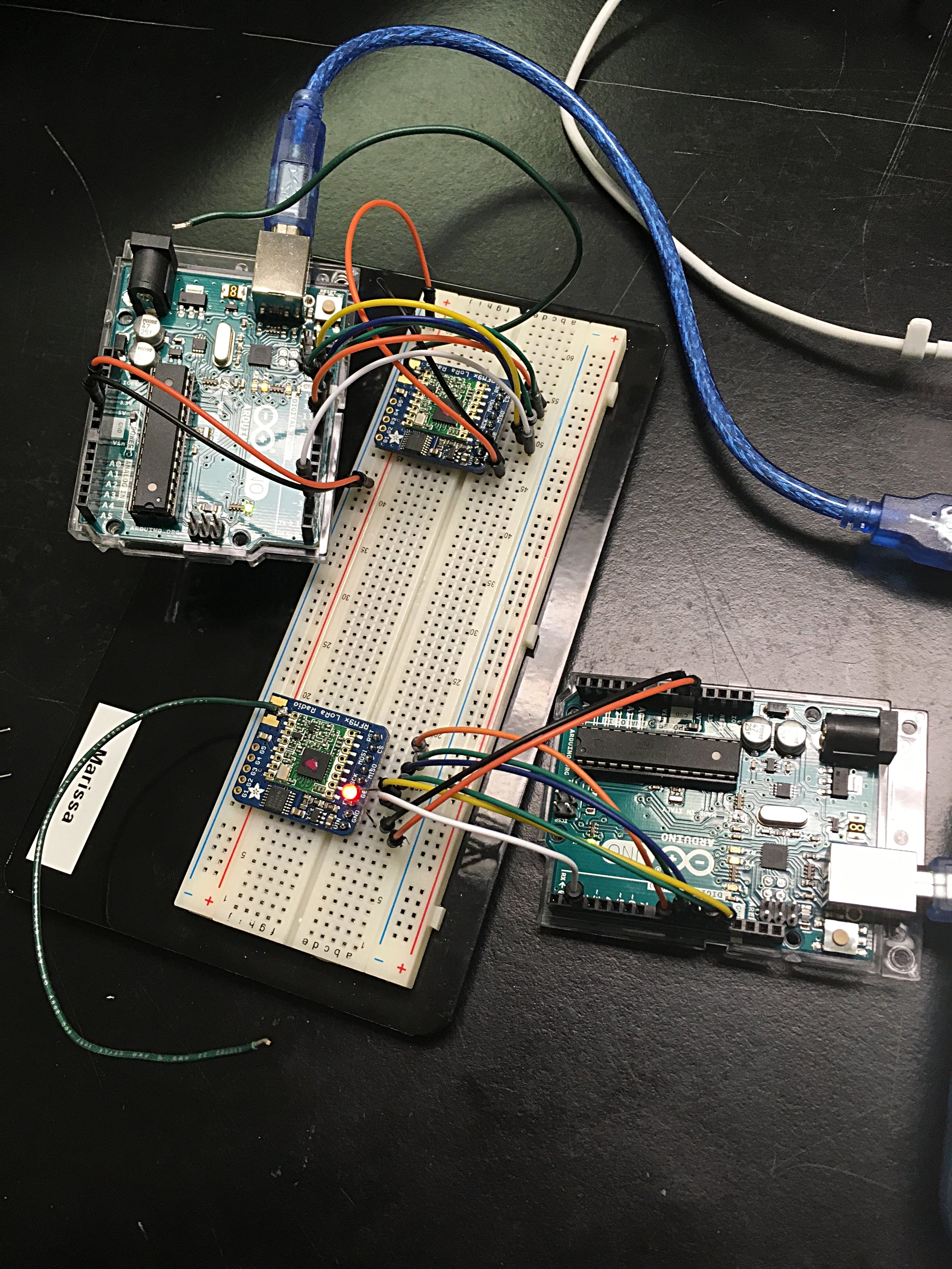
In this blog, one of our URSA Engage research students (Marissa K) got the LoRa radios up and running using this Adafruit tutorial. Below, she will detail what she had to do and modify to get this working with the RFM96W 433MHz breakout board – along with accompanying example code. These cost only $20.
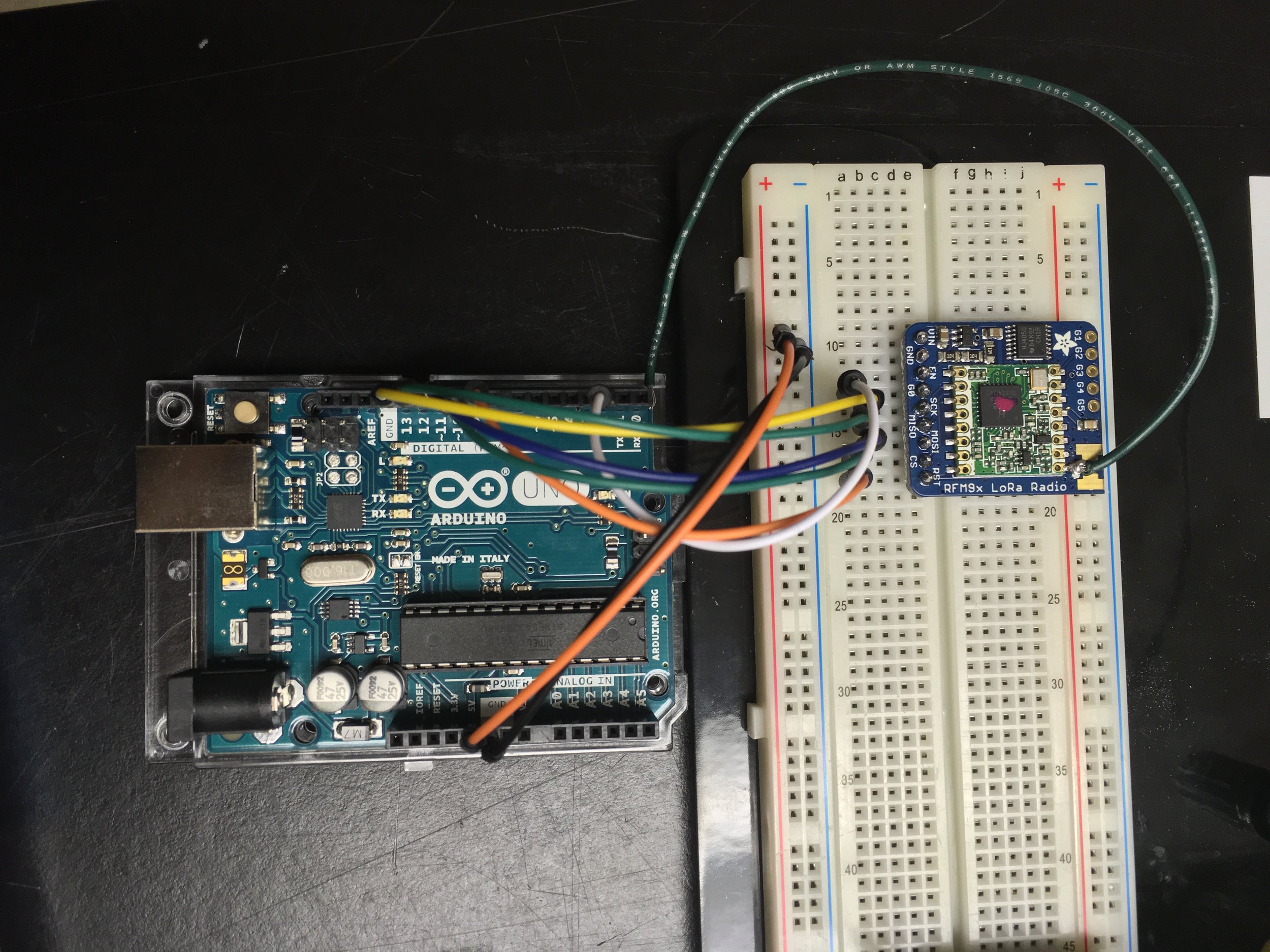
Arduino Uno connected to Adafruit’s LoRa RFM9x Radio Transceiver Module
Wiring:
Here’s the setup pictured above:
LORA Arduino Uno
Vin —————– 5V
GND ————— GND
GO (IRQ) ——— 2
SCK —————- D13
MISO ————– D12
MOSI ————– D11
CS —————— D10
RST —————- D9
GND ————— GND
Antenna connection – soldered a 6.5 inch wire (green) that corresponds to a frequency of 433 MHz
Note: The Arduino Uno is capable of supplying either 5V or 3.3V. For this project I went with the 5V supply since additional components used for collecting data from the surrounding environment will require a higher voltage and the LoRa pins use level shifting circuitry to safely power the chip with 3.3V-6V of direct current. With level shifting circuitry the MOSI on the LoRa radio operates on a 3.3V logic level while sensors connected to the power rails on the breadboard are powered with 5V.
LoRa Radio breakouts communicating; LED attached to designated “Receiver” LoRa Module
Code:
The source code used to program the LoRa radio’s to receive and transmit data came from the Adafruit website and AirSpayce’s Radiohead Library. In the Arduino IDE, the radio frequency was changed from 915.0 to 433.0 MHz. Here are the links for the code I used to program the transmitter and there receiver.
Serial Output:
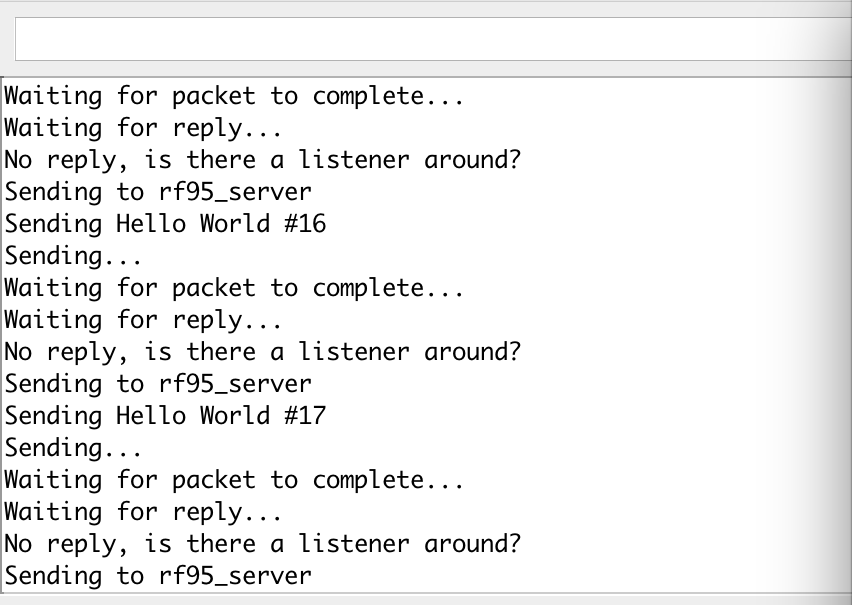
Once the transmitter Arduino was programmed and powered, it initialized and began sending signals awaiting a response from another radio unit on the same frequency. If no response was found, then the following output would appear on the serial monitor:
Transmitter radio without a recepient
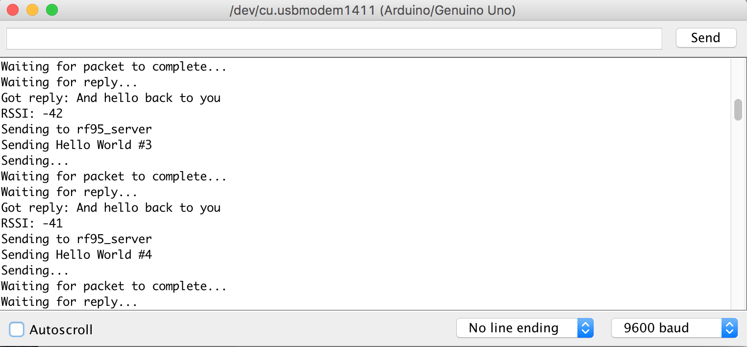
Once the receiver Arduino was programmed and powered the two began sending and receiving packets of information – in this case a simple message, RSSI signal strength, and a count incrementing after each successful exchange:
Communication between transmitter and receiver LoRa Radios; output printed to the serial monitor in Arduino IDE.
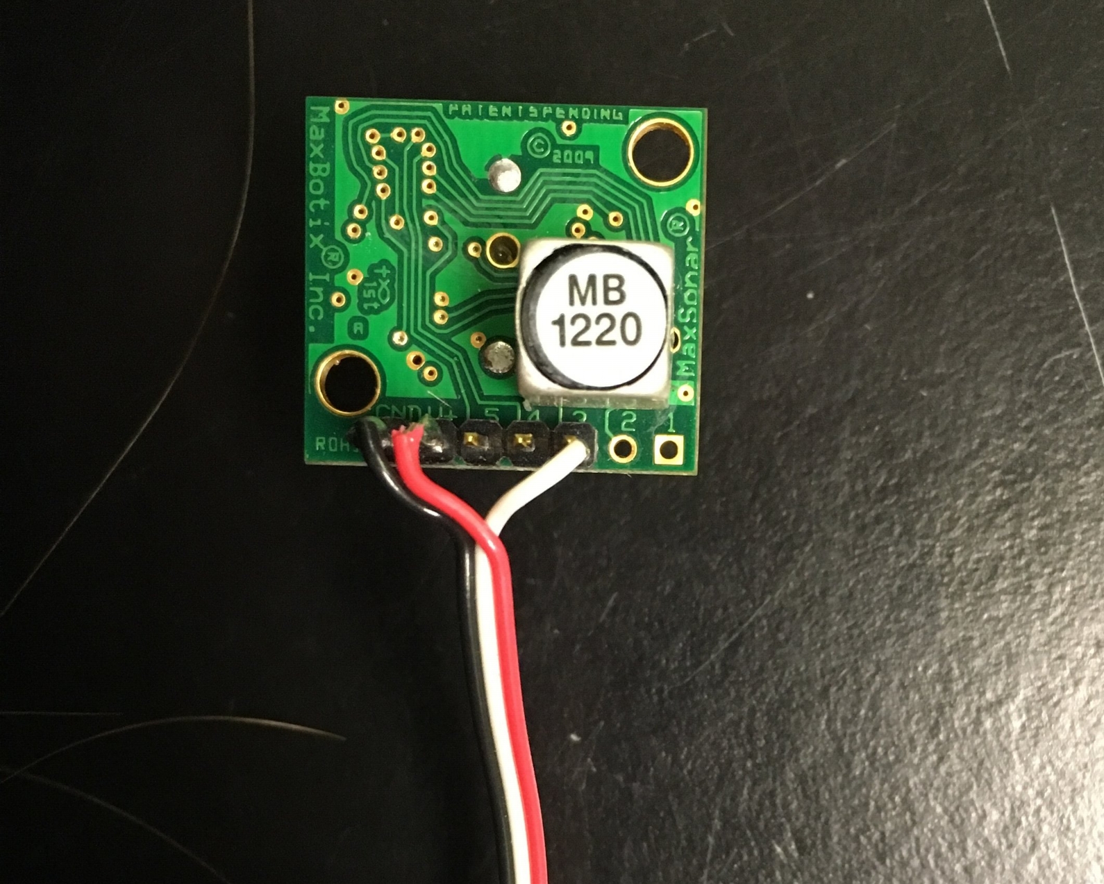
Now that the two LoRa radios can communicate we should be able to transmit raw data from one radio to another. The next step is to attach a sensor to the transmitter Arduino that collects such data in real time. Over the next few days I will be using Maxbotix’s XL-MaxSonar-EZ sensor to collect data and transmit that data to the receiver. The MB1220 sensor that I will be using detects objects within 15ft from the front of the sensor and outputs the distance away in inches when connected to the analog pin A0 on the Arduino and the breadboard’s ground and power rail supplying 5V.
For this project, we’ll need to construct a drone that will carry the RFID reader around a crop field. It’ll need to remember the locations of every new RFID ‘Dogbones’ moisture sensor it encounters, and store the GPS coordinates so that it can return to the sensor later. We’re not sure yet how much weight it’ll need to carry, which leaves a lot of the the specs of the drone up in the air. We’ve come up with a general parts list, however, which includes the following:
CC3D Flight Controller
750KV Motor (x4)
30A ESC (x4)
4000mah 3s battery
12×4.5″ propellors
650mm frame
Arduino Uno
GPS module
RC Transmitter/Receiver
Our idea for flying the drone autonomously involves hooking up the Arduino to the CC3D flight controller’s RC receiver pins, and simulating the 1000-2000us pulses that the flight controller would expect from a receiver with the Arduino. This way, the CC3D flight controller does all the low-level attitude hold and hovering work, while the Arduino is free to read the GPS sensor and control the position of the quad by pretending to be an RC receiver.
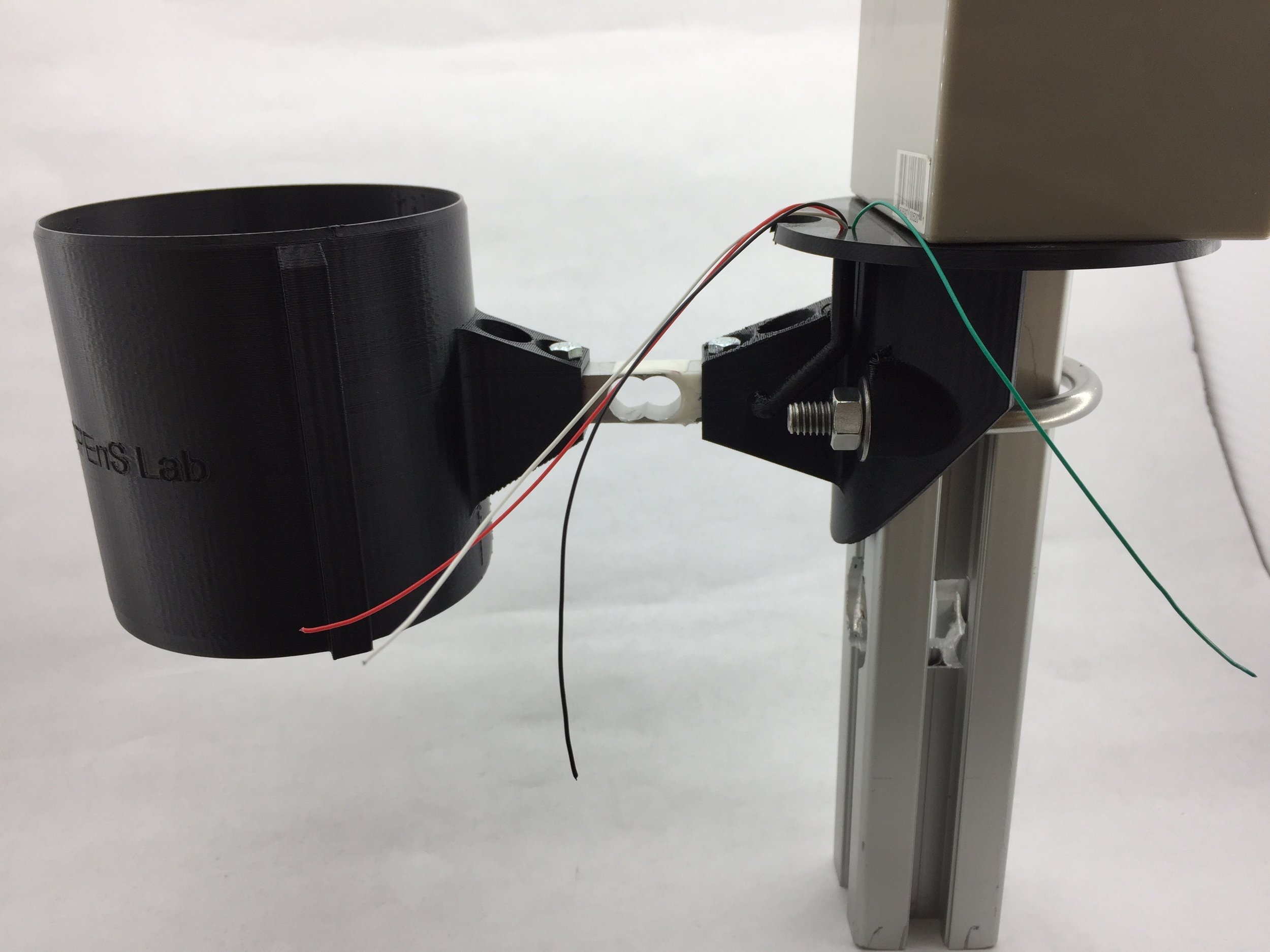
The system has been printed. There are so minor flaws with will be addressed, but we have our first prototype.
3D printed Validator and pole attachment
In the image above we can see both of pieces that are 3D printed. The pole attachment is locked to a piece of aluminum extrusion just for demonstration purposes; it also has a battery sitting on it to keep it from falling. Our validator has a 6mm hole diameter siphon and will drain all the container in about 50-55 seconds. An ADC will be amplifying the signal coming from the strain gauge and outputting data to an Arduino UNO. All the electronics will be located on top of the pole attachment.
The flaws that were previously mentioned were about the attachment. The holes for the u-bolt are a little bit too close so I had to drill them out to get the u-bolt to fit. Another thing that will be changed is the little tube on the side that guides the wires coming from the strain gauge. It has a 90-degree corner that makes it difficult to pass wires through it, so I will modify the design to make it smoother. Other than that, our desing is complete.
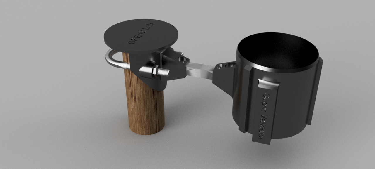
After many tests to figure out what would work out the best, we have chosen our best design. We will be using a 6mm diameter hole for the siphon, this will be sufficient for what we need it to do. I have been able to put together a model of the whole system to be able to visualize the prototype. Here is a rendering of the Super Validator configuration:
Super Validator system
This model only has the parts that will be 3D printed, the electronics will be sitting on the part that is attached to the pole. The electronics consist of a strain gauge connected to an ADC that will be sending data to an arduino.
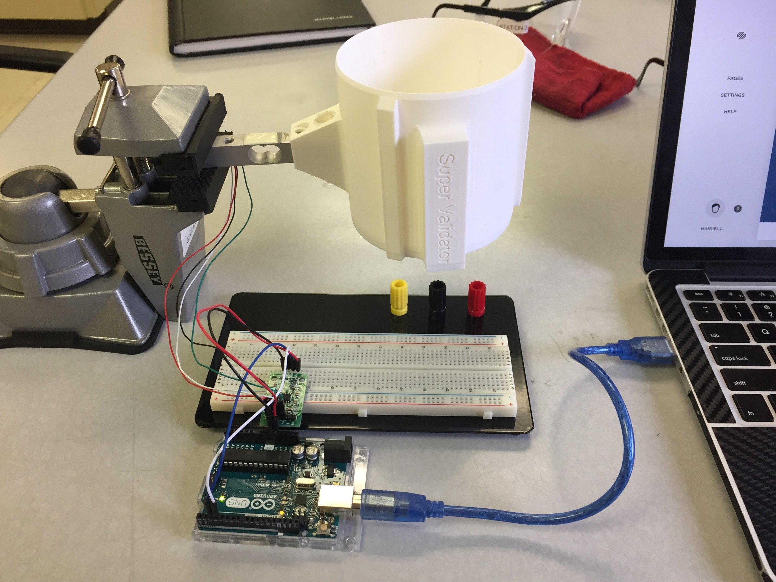
Electronics setup
The electronics have been calibrated and tested. We are currently printing both the validator and the pole attachement, and will soon have the first working prototype.
Hello all, today the RFID team figured out how to use the Cottonwood to communicate with the Dogbone tags. To celebrate, we measured the Dogbone tag’s RSSI value in wet and dry conditions. This was done to see if RSSI value could be used as an indicator of moist conditions.
RSSI value is a measurement of received signal strength. It’s an acronym for “received signal strength indicator”. It’s often used in WIFI signals. Here is a good article from MetaGeek that explains it further: http://www.metageek.com/training/resources/understanding-rssi.html
For this test, we read multiple RSSI values when the tag was dry first. We then wet a piece of paper behind the tag and recorded the RSSI values again. The picture below shows our setup. It should be noted that while wetting the tag we might have disturbed the system which would mean that our results will need to be backed up with further, more precise testing.
To receive the RSSI data, we sent an “Inventory Command with RSSI” command from the Arduino to the Cottonwood. The command was sent as a character array { 0x44 , 0x03 , 0x01 } and was taken from the Cottonwood’s datasheet. We got back a message that contained the RSSI value in the third byte of the response. Below is a table with the RSSI values measured in wet and dry conditions.
In conclusion, there might be a slight correlation with moisture, but further testing is needed. Also, the distance between the antenna and tag is a large factor in the RSSI value and should be taken into consideration before implementation.