ETA Attachment

Abstract:  I’ve bee working on the ETA attachment and here is an update on what it looks like and where the design will go next. 

Objective: The ETA is designed to hold the two light sensors and one humidity/temp sensor. The two light sensors will make the albedo measuring system, so one has to be looking up and one straight down. The humidity/temp sensor is going right under the light sensor that is looking straight up. 

Methods: I’ve been using Fusion 360 to do the CAD and I will be 3D printing on the Fusion3 F400.

Results:

Here is the attachment piece from the sensors to the hub of the electronics. This has a slide mechanism that makes it easily detachable. This piece has to be put in first before the cap because the caps actually functions as a lock for this piece, it keeps it from sliding out in case that something bumps it. 

This is a preliminary look at what the ETA will end up looking like. This rendering is still missing the disks that will be holding the two light sensors and the humidity/temp sensor. I had to do some redesign on the base to be able to accommodate the extruding piece of the ETA attachment, but I think that this piece is solid design and I can now move on to design in the bases for the sensors. 

The bases, which will look like little disks, will hold the sensors. The one that will go on the 360 swivel will hold a light sensor on top and the humidity/temp sensor underneath. The other disk will go on the underside of the swivel, it will only hold a light sensor. 


Sleeping Beauty; Low Power, RTC’s, and Sleeping Processors. – A guided walkthrough

By: Tom DeBell

Abstract

As our production of open source devices with a variety of sensors continues to roll out, it is of the utmost importance to try and make these devices as power efficient as possible in order to conserve battery life. The solution is simple, using a variety of adafruit and SparkFun libraries such a LowPower.h, RTClib and a custom RTClibExtended. However, the problem at hand is the compatibility and settle discrepancies between the processors we are using and how they interface with these libraries. This post will serve as a walkthrough on how to work with these power saving libraries with the latest 32u4 and M0 processor boards as well as integrating this logic into Arduino UNO projects.

Methods

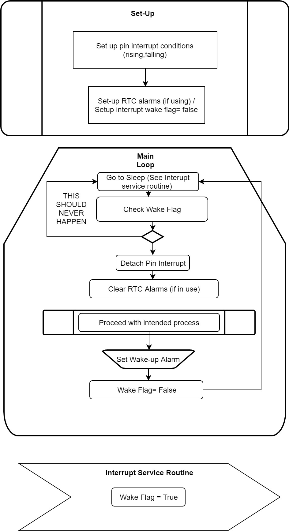
I think the best place to start off is a diagram of what a template program using sleep functionality should look like. Below is flow chart of sorts of how your program should be set-up in order to follow the structure of the example code included with this guide.


Sleep-RTC Logic Diagram (1).jpgSleep-RTC Logic Diagram (1).jpg

*Important note, any delays or program functions should be contained within a conditional statement in the wake flag routine. *

Using Pin Interrupts

Often times the simplest way to conserve battery is to put the processor to “sleep” which causes the device to enter a lower power state where it is no longer constantly checking all peripherals or running any processes. However, the most common (and simplest) way to wake a processor is to specify an interrupt pin. An interrupt pin is a specified digital or analogue pin that is expecting an interrupt signal (typically rising or falling voltage). An interrupt is a signal that tells the processor to immediately stop what it is doing and handle some high priority processing, in our case WAKE UP! Below is a brief breakdown of the different syntax used to initialize an interrupt pin on the 32u4 and M0 Adafruit processors boards as well as a basic Arduino.

Arduino Uno

– use A0 pin as an interrupt (using attachInterrupt function as laid out in the code provided)

Example Code:

32u4

– Use SleepWake32uPCINT

Example Code:

M0

– Use SleepWakeMoInt

Example code:

Using the DS3231 Real Time Clock to Send an interrupt signal

Note: There are two types of alarm styles (Wake up once daily, or after a certain elapsed time) included in the RTClibExtended library, Both are included in the linked sketches.

Arduino Uno

– use RCTSleepWakeUseIntA0

Example Code:

32u4

– use SleepWake32u4RTCPCINT

Example Code:

 M0

– use SleepWakeMoRTCInt

Example Code:

Conclusion

After looking at three of the most common processor boards and how to establish Pin interrupts and RTC interrupts, this tutorial should greatly increase the power efficiency of our future projects.

Tom DeBell

Capstone: Project Features

By: Travis Whitehead

For the past two weeks, we have focused our efforts on drafting and revising a requirements specification for our capstone project (as it is required for all capstone projects). This document is available on GitHub in our project’s fork of the OPEnSampler repo, under the “capstone” branch.

Overall, there are two major components to what we will be delivering over the course of this project:

  1. An Android app (that we’re calling the OPEnSampler Companion app) that will be able to update OPEnSampler’s settings and control it directly.
  2. GSM functionality allowing the OPEnSampler device to send status updates and information to specified recipients.

Companion App:

The primary purpose of the OPEnSampler Companion app is to replace the need for a physically connected laptop. It will be used to easily read and adjust the settings on an OPEnSampler device, and it’ll be a big improvement in usability over the serial command set currently implemented.

The OPEnSampler Companion app will be able to…

  • Pair with the OPEnSampler device over Bluetooth Low Energy
  • View and update the device’s settings, such as timer mode (daily vs periodic), sample rate/timer length, sample size, etc.
  • “Puppet” the device, instructing it to open/close valves or enable/disable the pump in either direction.
  • Specify recipients of status updates.

The app we’re developing will be for Android devices. Unfortunately iOS support is out of scope for our capstone project, but that’s something others could take on down the road.

Status Updates:

Status updates will allow an OPEnSampler’s users to receive information about the device and know what it’s up to. Currently we’ve been planning on supporting email and SMS (text message) notifications, but email is the primary focus.

The OPEnSampler will notify users when a sample is collected, or when all samples are collected, and these notifications will include timestamps. Once the OPEnSampler supports measuring battery capacity, it will also warn users of low battery life. We’d also like to send information about environmental sensors included in the Sampler (like temperature).

The Companion App will be able to specify the recipients of status updates, but we’re still researching the limitations of how many users’ email addresses or phone numbers can be stored on the OPEnSampler’s EEPROM (persistent memory that stores the device’s settings). If this turns out to be a problem, we’re considering a variety of options:

  1. We could allow users to hard-code extra recipients into the program itself (making use of flash memory, which is much larger than EEPROM), with the caveat that users would have to re-upload the program whenever they wish to change these.
  2. We could expand the storage capacity of the OPEnSampler with an SD card (which could be useful for other reasons, like if we wanted to do logging).
  3. Users could simply maintain a mailing list of status update recipients, and store only the address for that list in EEPROM.

Power Pulse Controllers Done!

Abstract: The Power Pulse Controller project has come to a conclusion. All three PPC’s have been made! Final testing is the next step to get them ready for use. 

Methods: N/A

Results: 

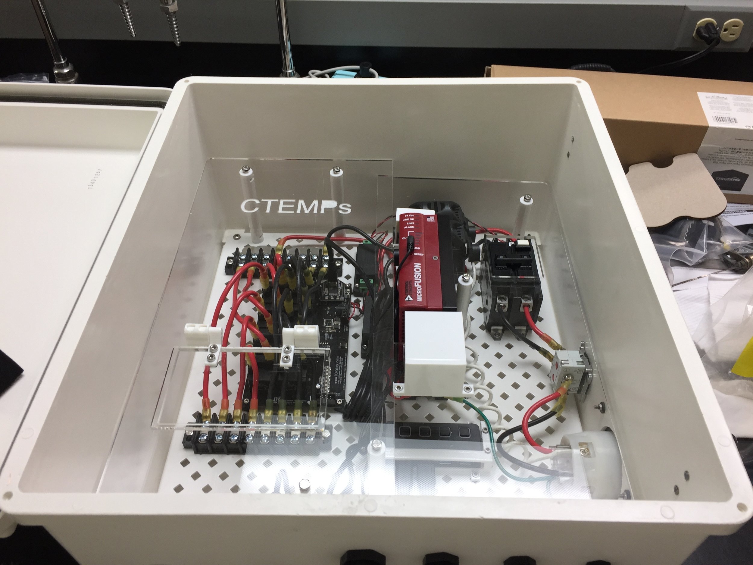
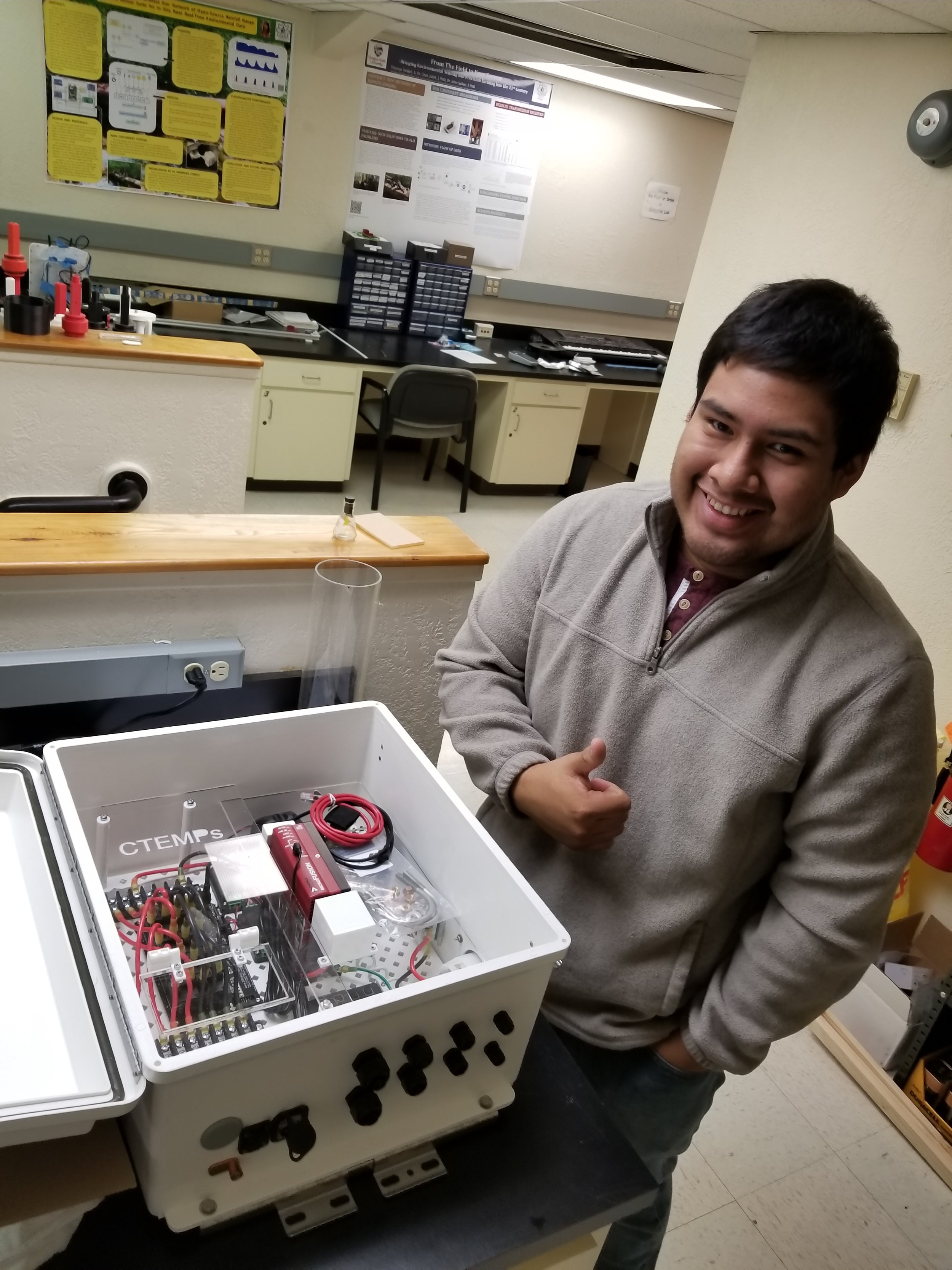
The following image displays a finished Power Pulse Controller. We sold one to Columbia University and have two in stock. I will get in contact with Jim Wagner to verify all the connections and test the units to make sure that they are ready.


Fully assembled Power Pulse ControllerFully assembled Power Pulse Controller

Fully assembled Power Pulse Controller


20171101_100329.jpg20171101_100329.jpg

System for Testing RFID Tags’ Ability to Sense Humidity

Author: Brett Stoddard

Hello  Everyone! 

For the past few weeks, I’ve been further examining the RFID Dogbone Tags. This time I’m testing their capability as capacitive humidity sensors. This article describes the system I built to test them out.

Abstract and Objectives

This blog post describes a system to log data from multiple Smartrac Dogbone RFID moisture sensing tags in the air over the course of the day. The goal of this system is to log the Dogbone’s moisture sensor levels vs a DHT11 Humidity and Temperature sensor. After logging data for multiple day cycles, enough data should be present to tell if there is a relationship strong enough between the Dogbone’s measurements and the DHT11. Further testing would be warranted if such a relationship exists.

To measure multiple tags at once, this system incorporates a HyperRail prototype. The HyperRail’s details can be found distributed throughout this blog page on the OPEnS site.

Materials

Libraries

Description


Results

Over the weekend the system was run. It gathered some data, but not enough to make a sure prediction of whether the Dogbone tags can be used as humidity sensors. However, this is an example of what the code output should look like.

Values of RFID, Humidity, temp, EPC, time, f

What data should look like when opened in Excel

Known Issues

As of now, the SD card will only log data when the Arduino is plugged into both USB. This shouldn’t be necessary because it is already powered by Vin. This issue is probably a power supply limitation of my specific setup, however, I thought it was worth noting here.

Shipping the OPEnSampler


IMG_0281.JPGIMG_0281.JPG

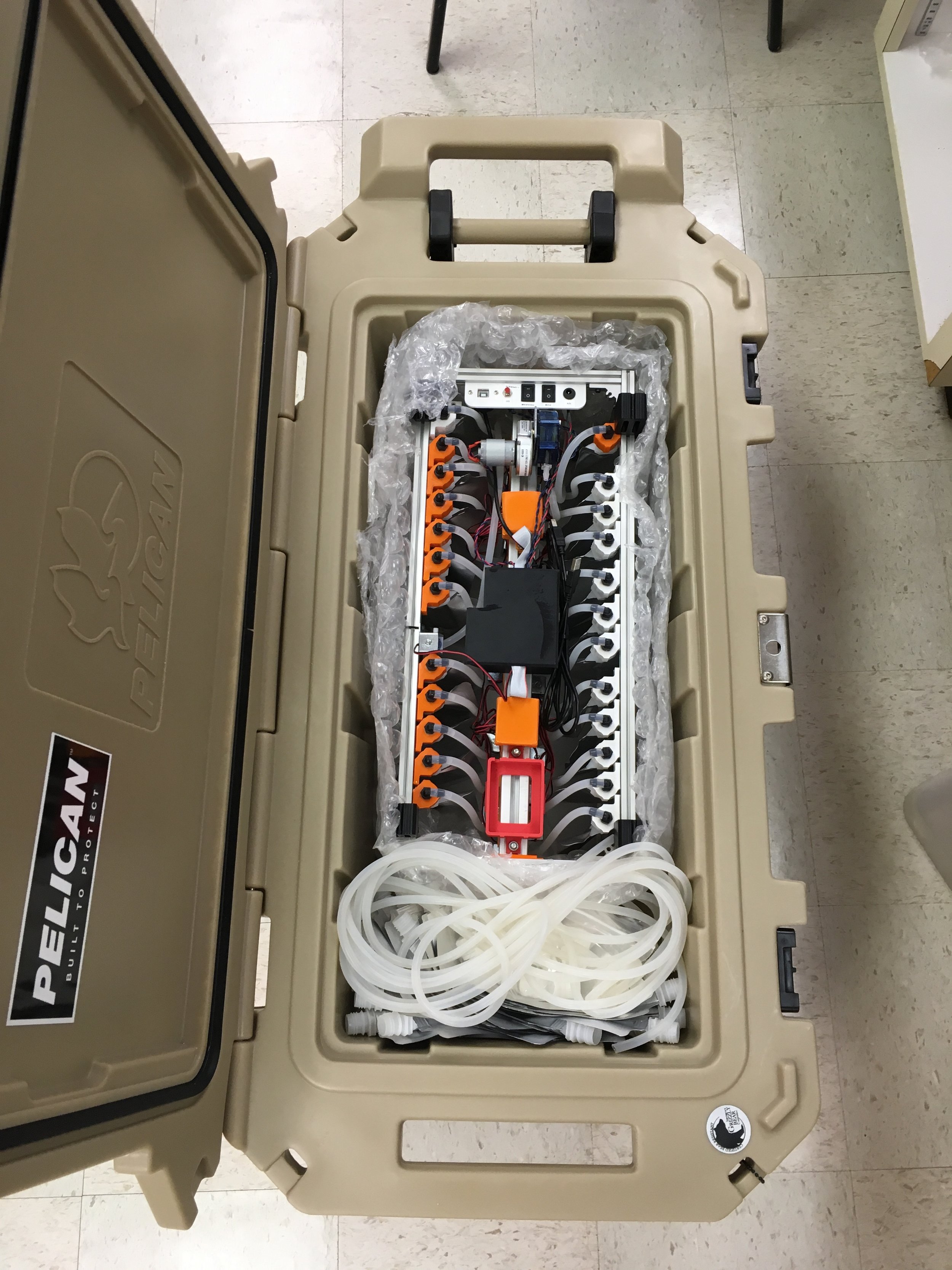
The late-summer OPEnSampler is shipping! We’ve come a long way from the foam puck concept with several iterations throughout the process. The team at Zurich will provide us with much needed field and user testing as we add more members to the team working on the firmware and companion software. Packed into the 80QT Pelican Rolling Cooler is the OPEnSampler, batteries and power supplies, spare tubing and bags, and lots of foam and bubblewrap. The sampler we are sending uses silicone tubing and the June 22 board, but samples effectively and reliably. The serial command interface allows the operator to plug in a laptop and tell the sampler when and how to sample, and the operator interface makes initiating the sampling process quite simple.

There is still much more development to be done! The next batch of samplers include many more features described in previous posts, such as GSM communication capabilities, power decoupling and filtering, and additional sensors to control the sampling process. The hard Teflon tubing will increase the quality of the sampled water and the new pumps, once integrated, will allow large-particle suspended sediments to be sampled with ease.

The next step is to update documentation. This has been a weak point in the design process and the changes and timing of one iteration to the next were not always transparent. Considering the purpose of the device is to be shared with the community of water sampling, you can expect more frequent and detailed updates on the designs following this milestone. I will be updating the GitHub page shortly with the latest and greatest .STL part files for our printed parts, documentation, and the new PCB board files. Later on I will be adding assembly instructions and new code will be posted. In the coming weeks there will be two of the new samplers on our lab tables: the bottle sampler and the bag sampler.Stay tuned!

Capstone Team Intro: Hunter Lien

My name is Hunter Lien and I am one of the new additions to the OPEnSampler team! I’m currently a senior here at Oregon State University getting my degree in computer science focusing on computer security. I first got into computer science back in freshman year of highschool when my school started a computer science program. Every level of the class was taught by a single teacher, Mr. Bartlo and I consider him the biggest contributing factor to my interest in this field. He always encouraged us to move outside our comfort zone and even helped us get funding for projects that might have required additional hardware.

Travis, Chase, and I make up the senior capstone group responsible for developing an Android application capable of interfacing with the OPEnSampler hardware. We will be working on this for the next 6 months at which point we aim to have a functioning product. All three of us will be posting weekly blog posts on the OPEnSampler website to let you all know how progress is going in whatever area of the application we happen to be working on. I’m really excited to get started with this project and can’t wait to be part of it’s success.

Capstone Team Intro: Travis Whitehead

A Bit About Capstone:

Earlier this year, OPEnS Lab submitted several project proposals to Oregon State University’s capstone course for computer science (CS) students. Capstone (or Senior Design) is a three-term course in which students work in small teams on projects that solve real-world problems. One of OPEnS Lab’s proposals was to enhance the OPEnSampler with GSM support enabling long-distance status updates, and to ease the sampler’s configuration with a mobile app that will communicate with the Sampler over Bluetooth. That’s where we come in!

I won’t go into too much detail in this post, but you’re welcome to read the problem statement we prepared for capstone, available in our fork of the OPEnSampler GitHub repository.

(If seeing PDFs in git hurts you, rest assured we’ll be doing some cleanup and reorganization in the near future.)

Right now, we’re mostly getting started by preparing written documents that will guide our future work. The week before last we finalized our problem statement, and this week we’ve been working on drafting a requirements specification. Although we don’t have an exact time-line laid out, our end game is to have completed this project by OSU’s Undergrad Engineering Expo during the Spring (where we will be presenting our contributions).

A Bit About Me:

I’m Travis Whitehead, a Computer Science student at OSU with the exciting opportunity to work on the OPEnSampler for my capstone project (along with my teammates Hunter and Chase– who will also be introducing themselves in separate posts). As I don’t have a lot of background experience with mobile development, microcontrollers, GSM, or Bluetooth specifically– I’m expecting to learn a lot this year!

As a free software enthusiast, I’m delighted about the “Openly Published” aspect to OPEnS Lab. In my spare time, I work as a Student Systems Engineer at OSU’s Open Source Lab a (similar sounding) organization that provides various forms of hosting for open-source projects. Luckily, there’s room in my heart for more than one open lab.

This is the first of many updates I’ll be writing as we continue to work on this project– So stay tuned!

Capstone Team Intro: Chase Coltman

Hello, my name is Chase Coltman, I one of the three capstone students working on the new companion app for the OPEns Lab Water Sampler, OpenSampler. I am excited to bring some of my previous mobile development experience to this project and make a great addition to this team. Currently, I am in my Senior year at Oregon State University, and I am studying Applied Computer Science, with a focus in Simulation and Game Programming. I am thrilled to be a part of this team and can’t wait to see what’s in store.

Previously here at Oregon State, I have taken several classes that will be very beneficial to our assignment. Two of the most beneficial classes I feel will contribute the most to this project are Mobile Software and Cloud Development, and Intro to Usability Engineering. My Mobile Software and Cloud Development class will likely be the most useful as we focused on app development, however we did not cover certain things like GSM or BLE, which is going to play a very large role in the companion app. My other class, Intro to Usability Engineering, was more about general UI design, good user/design focused elements such as Affordance, Consistency and of course Usability. 

Evaporometer 2.0 First Prototype

Abstract: Here is an update on the progress of the second versions of the Evaporimeter. We have now printed the pieces and mounted the electronics onto the 3D printed pieces. 

Objective: To inform the reader of the features and changes to the Evaporimeter design. 

Methods: I did all the CAD on Fusion360.  Here is the Assembly.

Results:

This is the CAD for the new design. 


This is the first prototype of the second version. We have to yet test the whole system, but we are getting there. There are some minor things to fix first before this design of finalized. 

This version has a barrel jack that will be used for solar power charging; this was intended for an external solar panel attachment. We are planning to integrate the solar panel into the project’s electronics, so we will be8 making a new base cap that has the solar panel in it and the electronics on the underside.

This design also gives the user access to uSD and USB by just sliding a cap off. This will be very nice when you have to get the data from the uSD card or you have to reprogram the microcontroller. 

The solar shield on this design is outdated. I want to make an octagonal version of the shied that will cover all the sides of the strain gauge. This will make it so that the heat is more evenly distributed.